Spring 2021
Jonathan Ochshorn

| Concepts | Systems | Elements |
Equilibrium Force-moment-stress relationships Deflection/deformation |
Tall building systems Long-span systems Lateral-force-resisting systems Lateral loads (wind, seismic) |
Design of wood, steel, and reinforced concrete elements (focus on beams; conceptual discussion of columns and tension elements using calculators) Discussion of material properties and construction/connection strategies* |
* Includes structural masonry properties, manufacture, and systems.
| Wood | Steel | Reinforced Concrete | Masonry | |
| Bending | Wood joists and beams | Steel beams and girders | Reinforced concrete T-beams | Not considered |
| Tension | Quick overview using calculators | Quick overview using calculators | not considered | Not considered |
| Compression | Quick overview using calculators | Quick overview using calculators | Quick overview using calculators | General rules of thumb for walls |
| Construction of structure | Systems and properties | Systems and properties | Systems and properties | Systems and properties |
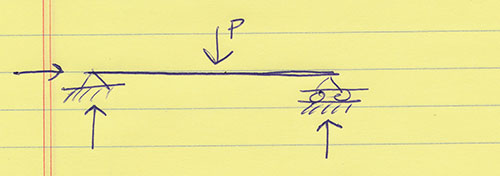
In the "Concepts" course, only determinate structures were analyzed; these are structures where the number of constraints equals the number of equilibrium equations. For 2-dimensional ("plane") structures, there are 3 equations of equilibrium (vertical, horizontal, and moment) based on the fact that the sum of forces (or moments) in any direction must equal zero. This means that we only analyze structures with 3 constraints (or 4 constraints and one internal hinge), such as the famous "simply-supported beam" that is typically invoked for most wood or steel elements:
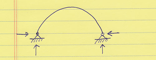
Indeterminate structures, on the other hand, have more than 3 constraints, as in this 2-hinged arch:
In general, indeterminate structures are stronger and deflect less than determinate structures, all things being equal. However, determinate structures are (1) easier to design and (2) better at accommodating foundation settlement or other deviations from their ideal geometry caused by errors in fabrication, or differential movement. Indeterminate structures can be designed by finding additional equations, not based on equilibrium, so that the total number of these equations equals the total number of constraints. Such equations are based on compatibility of deflections, so that information about the relative stiffness of structural elements must be determined. None of this information is needed for the design of determinate structures. Virtually all indeterminate structures are designed using computational tools (structural analysis software), some examples of which are available online, including this free 2-D structural analysis software for the Mac.
We often place live and dead loads on structural elements, especially on floor beams (roof beams and columns also often have snow and/or construction loads to consider; and elements that are part of a lateral-force-resisting system have wind and seismic loads to consider). Dead loads are computed pretty much as one would imagine: by finding the weights of the permanent parts of the building, including the structure. Live loads, on the other hand, are determined by code agencies based on empirical and theoretical research and then adopted by the separate states into building codes. For example, a typical office occupancy is set at 50 pounds per square feet (50 psf). In NY State, the 2015 Building Code has tabulated values.
But it doesn't make sense to apply these distributed loads in the same way for all structural conditions: these loads are based on a maximum ordinary expectation that they could occur on any given small floor area, but it is unreasonable to assume that this intensity of load will occur over a large floor area. So, if a structural element supports a large floor area, we can reduce the live load acting on that area, based on this equation:
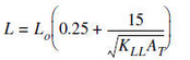
In this equation, Lo is the non-reduced (code-based) live load; KLL is the live load element factor, which can usually be taken as 2 for beams and 4 for columns (with some exceptions; see text for details); and AT is the tributary area of the structural element.
Here it is in a graphic form: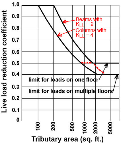
There is un upper limit of 1.0 for the "coefficient" (the part of the equation in brackets) and also a lower limit of 0.5 for loads on one floor, and 0.4 for loads on multiple floors. This means that a column at the bottom of a 100-story building (with an enormous tributary area) will have a live load equal to 40% of the load that would have been computed based on the Code values.
There are some important exceptions: live load reduction does not apply for live loads greater than 100 psf; and there are some other restrictions for things like 1-way concrete slabs, or for occupancies where the full live load can be expected to occur (parking garages, stadiums, etc.).
Here's an example of a live load reduction calculation for an office occupancy (50 psf). Consider a 5-story building with a 40-foot x 40-foot column grid.
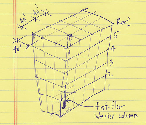
A typical interior first-floor column therefore has a tributary area of 40 × 40 = 1,600 sq. ft. per floor, and supports a total live load tributary area on four floors (i.e., floors 2, 3, 4, and 5 — there is no live load on the roof). So, the total tributary area for the first-floor column is 1,600 × 4 = 6,400 sq. ft. We use a live load element factor of 4 (for columns), and so the coefficient is: 0.25 + 15 / sqrt(4 × 6,400) = 0.34. But the lower limit for multiple floors is 0.4, which governs in this case. We therefore design the first-floor column based on a live load of 0.4 × 50 = 20 psf. In other words, the total live load acting on the column is assumed to be distributed live load × tributary area = 20 × 6,400 = 128,000 lbs = 128 kips.
Of course, there is also a dead load, and possibly other loads, acting on this column, but we'll consider the combination of various loads later in this course.
Disclaimer: Students are responsible for material presented in class, and required material described on course outline. These notes are provided as a tentative outline of material intended to be presented in lectures only; they may not cover all material, and they may contain information not actually presented. Notes may be updated each year, and may or may not not apply to non-current versions of course.
first posted Jan. 27, 2016 | last updated: Feb. 6, 2021
Copyright
2016–2021 J. Ochshorn. All rights reserved. Republishing material on this web site, whether in print or on another web site, in whole or in part, is not permitted without advance permission of the author.