Jonathan Ochshorn
The building enclosure consists of four "environmental" control layers, not always articulated as separate layers, and not always present to the same degree.
These layers can be characterized as:
Watch only the first two minutes of this video...
Insulation and heat flow
Purpose of insulation
How heat flows
1. Conductivity (conduction)
Resistance, R = 1/C or l/k; i.e, it is the inverse or reciprocal of U-value.
Rt = R1 + R2 + ... + Rn
To find U: U = 1 / Rt. Note that U is not equal to C1 + C2 +...+ Cn
Heat flow, Q = U x A x (temp. differential) expressed in BTU/hr. units.
Example of U-value calculation for a 10' x 10' wall consisting of three layers as follows:
Note that these numbers are adjusted to make the calculations easier, but they are close to reality.
Rt = 0.5 + 19 + 0.5 = 20.
U = 1 / Rt = 1/20 = 0.05.
Calculate heat loss assuming an outside temperature of 20 deg F and an inside temperature of 70 deg F (so the temperature differential is 70 - 20 = 50 deg F).
Q = (0.05)(100)(50) = 250 BTU/hr.
Separate heat flow calculations could be made for all parts of the enclosure, including walls, roofs, windows, etc., and the resulting partial heat flows can simply be added together to obtain the heat flow for the entire building, or any given space. It is this number that then determines the size of a heating or cooling unit.
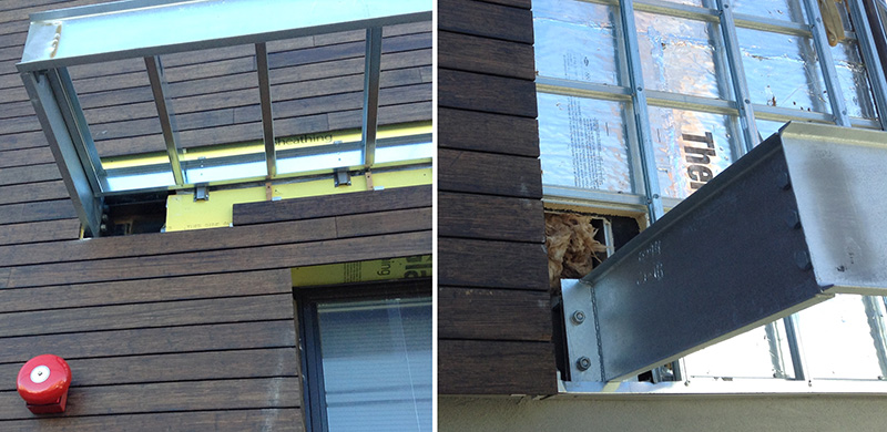
Thermal bridges are elements of construction that violate the continuity of the thermal control layer. They should be avoided, or at least minimized. Cladding systems, or elements that extend beyond the building's cladding, are often the primary cause of thermal bridging, since they need to penetrate the thermal control layer in order to be fastened to the thermally-protected structural system.
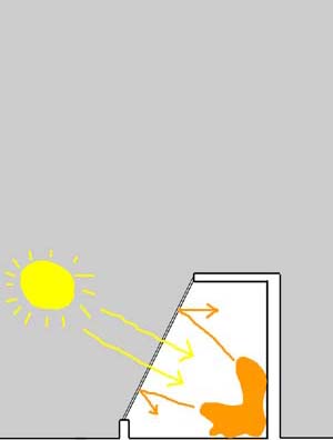
2. Radiation
3. Convection
Note that air is a good insulator if convection is prevented:
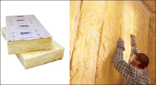
Insulation
Insulation takes many forms, including the following:
Fill: rockwool, fiberglass, perlite (expanded volcanic rock), vermiculite (hydrated magnesium alum. iron silicate)
Foamed plastic (rigid insulation): polystyrene, polyurethane, polyisocyanurate
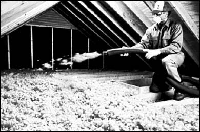
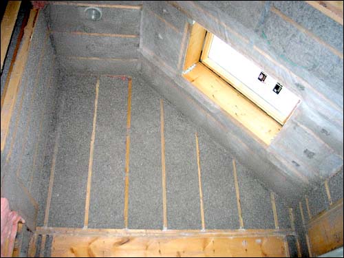
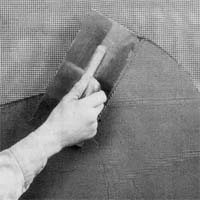
Sprayed-on: organic material (cellulose, etc.) or cementitious material (various proprietary products)
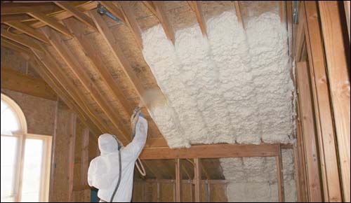
Spray foam insulation: two parts (foaming and hardening agents) combined while forced under air pressure into cavities or voids (polystyrene, polyurethane, glass, other phenolic base thermosetting foams)
Spray Polyurethane Foam Under Fire in CA
Monday, June 26, 2017
The California Department of Toxic Substances "initiated the proposal in March [2017] under the Safer Consumer Products program to list SPF based on its unreacted methylene diphenyl diisocyanates. If this listing is adopted, the designation would require manufacturers to complete an alternatives analysis and the DTSC could impose regulations. The proposal summary says that SPF has been put forth because 'workers and consumers could be exposed to unreacted methylene diphenyl diisocyanates during normal use of spray polyurethane foam systems. Inhalation and dermal exposure to unreacted MDI is associated with adverse health effects, including asthma and allergic sensitization. People who become sensitized to MDI may also experience life-threatening asthma attacks when subsequently exposed to extremely low levels of isocyanates.'"
Batts or blankets: typically fiberglass. Batts are coordinated with typical stud/rafter/joist spacing, i.e., manufactured to fit into spaces 16" or 24" on center. Blankets cover broad areas (e.g., over suspended ceilings) and do not need to be coordinated with stud spacing.
Radiant insulation is essentially any light colored or shiny surface. Note that such a surface must have air (or vacuum) in from of it to work. A light-colored roof (e.g., a white metal roof) is an effective example of a radiant insulative material, as it reflects the sun's energy before it gets a chance to enter the building. Note that this is useful only for buildings where cooling is the major energy issue.

This layer usually is what the "architecture" is made out of: including the facade and the roof. In traditional masonry buildings, rain (water) is controlled by the masonry itself, which deflects most water, but is thick enough to absorb some water without damage to interior finishes, after which the water evaporates, either to the inside or outside of the building.
In other schemes, the outside surface of the building is designed to repel water; in such cases, the surface must be perfect, with no gaps or holes, since there may be no means of absorbing water that penetrates the outer surface.

In modern construction, an air-water barrier may be placed behind the "cladding" or rain-screen, so that the visible surface of the building is designed to deflect most, but not all, wind-driven rain. More on these approaches later...
Condensation
A. dew point = temperature at which water vapor in air becomes liquid (i.e., condenses).
Hotter air can hold more vapor than cold air; as temperature is lowered, dew point temperature will be reached.
Dew point temperature corresponds to the amount of moisture (humidity, not "relative humidity") in the air: the dew point will be higher for air containing more moisture than for air containing little moisture.
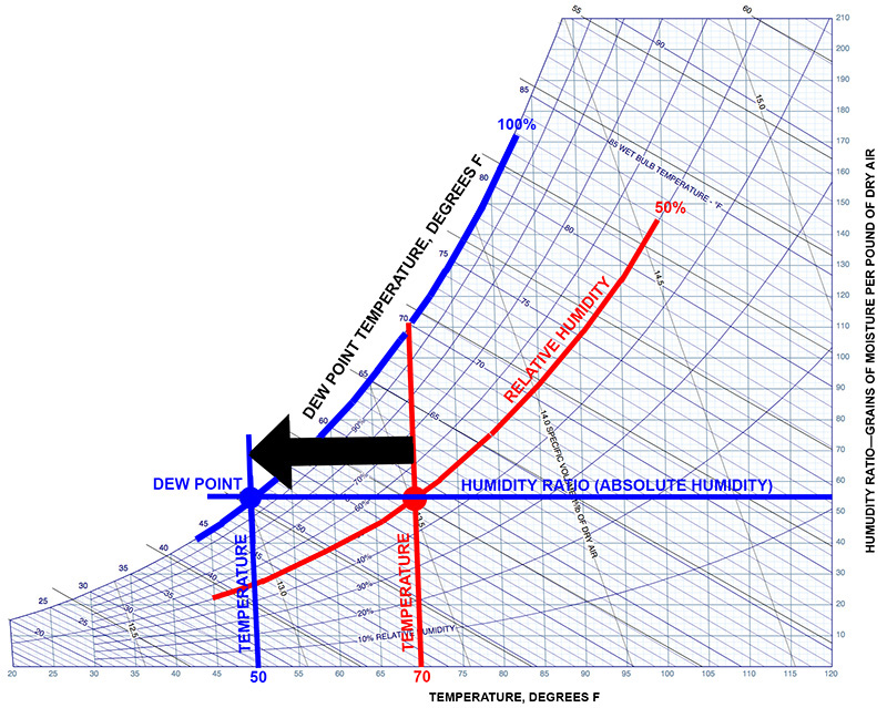
Psychrometric charts show the relationships among temperature, absolute humidity, relative humidity, dew point, and many other things. In the chart below:
Start with a given state of temperature and relative humidity, shown by the red lines. The temperature is 70 degrees F, and the relative humidity is 50%.
Next, to find the dew point temperature corresponding to this state of temperature and relative humidity, move to the left from the red dot along the "absolute humidity" line until you reach the point of 100% saturation or 100% relative humidity, shown by the blue dot.
The vertical blue line going through the blue dot indicates the dew point temperature of 50 degrees F.
B. Permeability: measures movement of vapor through material (in units of "perms"). See also more detailed permeance example.
Note that 1.0 perm or less is considered adequately impermeable to act as a vapor retarder; while greater than about 5 perms constitutes a permeable material.
The relationship between insulation, vapor retarders, and condensation is illustrated and discussed in my exterior wall psychrometric analysis calculator.
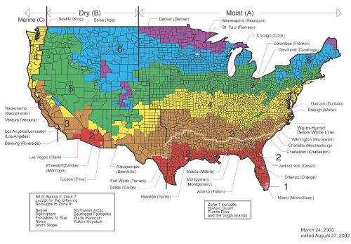
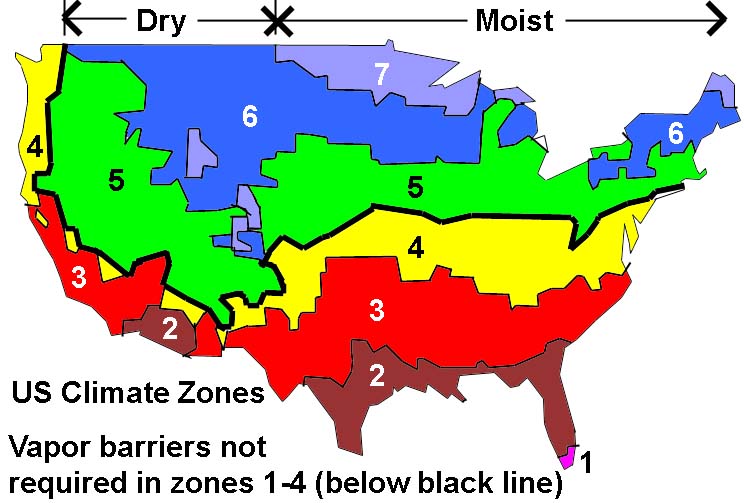
The use of a vapor retarder in climates that are always is fairly straightforward: it should be applied on the inside (warm) surface of the wall, typically immediately between the insulated wall studs and the interior finish material. Similarly, a vapor retarder in climates that are always warm and humid and in which interior spaces are air conditioned (cooled) does not present conceptual problems: it would be placed on the outside (also the warm side) of the wall. Where building walls are subjected to both hot-humid and cold climates during different seasons, the problem is more complex and is influenced by the building's climate zone:
In general, it is important to create an air space between cladding and sheathing so that rain water that works its way in from the outside, or water vapor that condenses within the interstitial space of the wall, has a chance to dry out.
See this concise article on where to put vapor control layers.
And see this interesting article on vapor pressure, explaining the causes of paint bubbling on the surface of a building and tea bags expanding in hot water.
Air barriers and infiltration
A. Basic air barrier theory: Moisture moves through material either by diffusion (based on permeability of material) or leakage. Leakage can be the more serious mechanism, with up to 400x more water conveyed.
B. Why vapor barriers are different: Vapor retarders work to prevent diffusion of moisture, but not necessarily leakage or infiltration of air.
C. Air barrier composition: Air barriers are designed to prevent infiltration, and consist of different materials within the building envelope with the following characteristics:
Infiltration (leaking) of air into and out of buildings can cause serious building envelope problems including:
Generally caused by various mechanisms that create differential pressure between inside and outside; requires "hole" in building, but such holes are common (gaps, tolerances, cracks, expansion, contraction, and so on, all can lead to holes). The differential pressures result from:
Five forces can drive water into a building:
Air pressure differentials are the most important; in addition to the force that results, two other things are necessary for the water to be driven into the wall: an opening ("hole"), and the presence of water on the surface of the wall. Overhangs on short buildings are effective means of keeping water off of walls, but generally are not effective on tall buildings. Eliminating all openings ("holes") is difficult to accomplish, as buildings consist of so many discrete parts, are subjected to extreme environmental conditions and structural movement, are built by contractors who are in a hurry to complete the job at a profit, and are designed by architects who may not have continuity of the building envelope surface as their primary design concept. On the other hand, air pressure differentials can be addressed through rain-screen or pressure-equalization theory. The idea, illustrated in the diagram below, is that a pressure-equalization chamber (cavity) can be vented to the outside, and sealed on the inside with an air barrier; wind pressure causes air to enter the chamber until the pressure inside the chamber is in equilibrium with the pressure outside; at that point, rain will no longer enter the wall: problem solved.
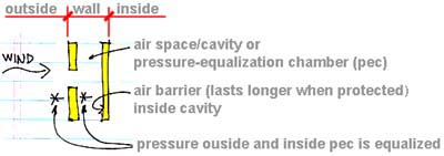
Of course, this all assumes a steady-state wind condition. In reality, the wind pressure is constantly shifting, even changing from positive to negative, and the internal "pec" pressure is constantly seeking to reach equilibrium with the outside pressure. This leads to periods of time when rain does enter, and other periods when rain is "sucked" out. In any case, it is necessary to drain the cavity so that rain that does enter can find a way out. Ideally, one would want a rain-screen wall that minimizes the so-called "time to equalization" under conditions of positive pressure, but maximizes the time to equalization during periods of negative pressure (so as to force water out of the "pec"). If pressure on the rain-screen is minimized (it can never be eliminated), one can also reduce the size and strength of the rain-screen cladding, saving weight and money.
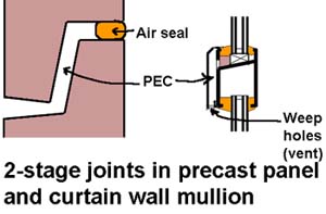
Other applications of pressure-equalization theory: So-called "2-stage joints are an application of rain-screen theory to the design of small joints, e.g., between metal or precast panels, or in curtain wall mullions. In the diagrams below, the joint (or mullion) is sealed at its back face, leaving the front open, vented, and drained. This creates a mini-"pec" within the joint that pressurizes in response to wind-driven rain, thereby keeping the rain out of the joint. It may, on the other hand, be difficult to install and maintain the seal, since it is not accessible from the exterior.
(from ASHRAE Journal, Feb. 2008, Joseph Lstiburek, "The Perfect Storm Over Stucco")
Traditional stucco construction (3-coat) performed well. Modern systems have experienced problems.
Solution: use a ventilated air gap between the stucco and building paper/OSB (3/8" will do). For example, a drainage mat can be used. This also helps in the other direction; allowing humidity from inside to escape without condensing within the outer layers of the wall assembly.
Solution: Recommends use of water-managed EIFS, with a drainage space and without an interior vapor barrier.
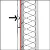
1. Face-sealed barrier wall: no redundancy; single surface intended to prevent air-water-vapor penetration; thermal control may or may not be within this single surface; includes systems like EIFS, stucco, concrete, and CMU.
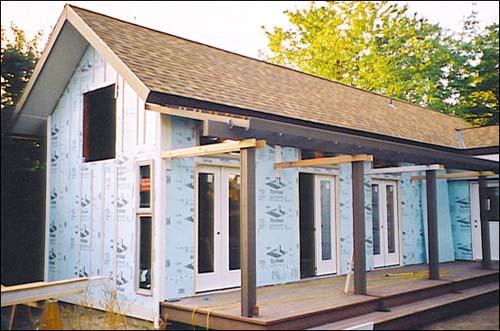
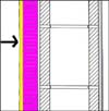
2. Internal drainage plane wall: contains at least a layer of building paper or "house wrap" (e.g., Tyvek) under the outside finish material; therefore has some redundancy, since it can block air-water that gets by the first line of defense; includes systems like some stucco and EIFS, as well as wood, fiber-cement, and vinyl siding systems. Vapor control is typically on the inside face (the "warm" side) of the thermal control layer and takes the form of a vapor retarder, e.g., 6 ml polyethylene sheets. Air and some rain water control is a function of the "house wrap," e.g., Tyvek, that is placed on the outside surface of the exterior sheathing.
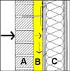
3. Drainage cavity wall: Contains an explicit cavity within the wall to intercept water and divert it back out, and , more importantly, to let any "wetness" in the cladding or interior wall elements evaporate into the cavity; the classic example is the brick-CMU (or steel-stud) wall. In the diagram, A = cladding; B = cavity; and C = back-up wall.
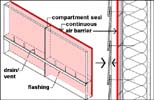
4. Pressure-equalized rain-screen wall: A variation on the cavity wall that explicitly provides openings (vents) in the outer cladding or rain-screen; to do this right, one really needs to compartmentalize the cavity or pressure-equalization chamber (pec), and to install a continuous air barrier to seal the inner surface. See the recommendations of Ronald Brand below.
Wall strategy diagrams adapted from Brock, Designing the Exterior Wall, Wiley (2005)
For an excellent summary of wall strategies, see The Perfect Wall
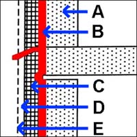
The key diagram is reproduced below, with additional annotations as follows: A = the structure and back-up wall structure (notice the space between the top of the back-up wall and the structural slab to allow for movement); B = the air barrier (notice the allowance for movement where the air barrier spans the "void" at the intersection of wall and slab) including flashing to drain the cavity; C = insulation tight against the air barrier; D = a drainage cavity (or pressure-equalization chamber if detailed rigorously); E = the rainscreen/sunscreen.
Joseph Lstiburek's excellent overview of control layer theory as it applies to exterior walls can be found here.
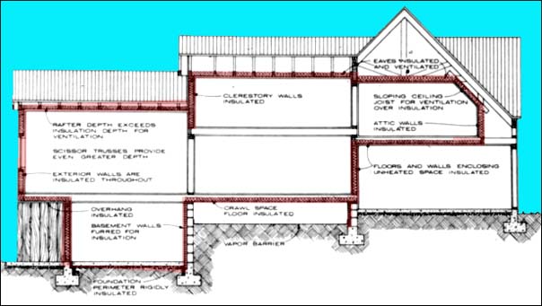
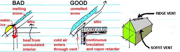
Ideally, one would "ventilate" the building envelope on the side opposite the vapor barrier, so that any stray humidity would not build up within the wall. In traditional wood-frame construction, a shingled wall provides such a ventilated space, since humidity can work its way through the relatively permeable outer layers of the wall. In sloping rafters or unheated attic spaces, the ventilation should be made more explicit, using soffit and ridge vents to promote the flow of air below the roof surface.
Ice dams may form over the eaves of roofs that are not properly insulated and ventilated: heat rising from occupied spaces melts snow on the roof; the melted snow freezes over the unheated eaves, forming an ice dam that blocks the flow of melted water. This pool of water works it's way through the roof shingles and into the wall, causing damage (see diagrams and image of the Foundry below).
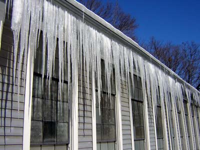
The Foundry at Cornell, Ithaca, NY (designed by Charles Babcock; erected in 1890 as a blacksmith shop and foundry for the Sibley College of Mechanical Engineering, from plans by Assistant Professor Alfred B. Canaga)
Photo by J. Ochshorn, 2007
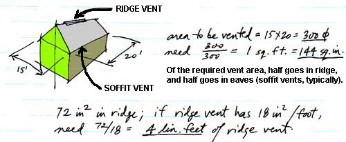
The basic rule of thumb for attic ventilation is to supply vent areas equal to 1/300 of the horizontal attic area, where the vents are split more or less equally between the ridge and the soffit and where—in climate zones 6, 7, or 8—a vapor retarder is placed on the warm-in-winter side of the attic ceiling (see Section R806 of the 2015 IRB. Otherwise, supply vents equal in area to 1/150 of the attic floor area.
See Architecture's Dysfunctional Couple: Design and Technology at the Crossroads for my discussion of control layer theory and architectural pedagogy.
Disclaimer: Students are responsible for material presented in class, and required material described on course outline. These notes are provided as a tentative outline of material intended to be presented in lectures only; they may not cover all material, and they may contain information not actually presented. Notes may be updated each year, and may or may not not apply to non-current versions of course.
first posted Aug. 24, 2007 | last updated: Feb. 16, 20260
Copyright
2007–2019 J. Ochshorn. All rights reserved. Republishing material on this web site, whether in print or on another web site, in whole or in part, is not permitted without advance permission of the author.