
Contents | 1. Introduction to structural design |
Introduction to loads | Dead loads |
Live loads are nonpermanent, or movable, loads within buildings caused by the weight of people, furnishings, storage of objects, etc. They are relatively unpredictable, vary over time, and are often dynamic, rather than static, in their application. Since it is not possible to measure these loads absolutely, a probabilistic approach is used: values are assigned to various types of occupancies based on "worse case" expectations, taking into consideration actual observed loading conditions and the historical record of structural failures.
Since these determinations are generic to various occupancy classifications, and are not unique to each structure, the problem of determining live loads is taken out of the hands of building designers altogether, and appears as a mandate of government in the form of building codes. Within these codes, the actual complex behavior of live loads is reduced to an array of uniformly distributed values, one for each type of occupancy. Examples of these live load values are listed in Appendix Table A-2.2.
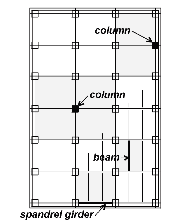
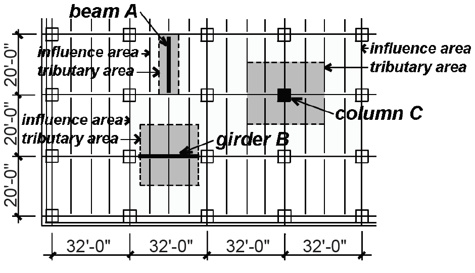
As floor areas become larger, it becomes increasingly improbable that the full live load will ever be present; therefore, a reduction in live load is generally permitted for structural elements "influenced" by relatively large floor areas. These so-called influence areas are different from the tributary areas used to compute "unreduced" loads — they are, in fact, four times larger for columns and two times larger for beams (Figure 2.4).
For this reason, a single reduction equation based on tributary areas cannot be derived for both columns and beams; instead, such a formula is written in terms of what used to be called the influence area, AI, but is now defined in terms of the tributary area, AT (ft2), times a "live load element factor," KLL:

Live loads are thus calculated by multiplying the tabulated values from Appendix Table A-2.2 by the area-dependent reduction coefficients (Equation 2.1), where KLL is defined in Appendix Table A-2.2, but equals 2.0 for most beams and 4.0 for most columns. The reduction coefficient is subject to the following limitations: (1) no reduction is allowed for values of KLLIAT smaller than 400 ft2; (2) no live load reduction is permitted for elements supporting a single floor with live loads greater than 100 psf (and for elements supporting more than one floor with live loads greater than 100 psf, no reduction greater than 20% is permitted); (3) no reduction coefficient smaller than 0.5 is allowed for ordinary beams or columns supporting one level only; and (4) no reduction coefficient smaller than 0.4 is allowed for any other condition, i.e., for columns or beams supporting more than one level.
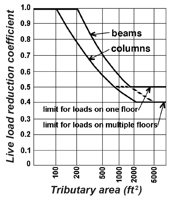
Live load reduction coefficients are plotted in Figure 2.5 for various tributary areas, shown separately for beams and columns. Notice that as the tributary area gets larger (and the likelihood of the full live load being present decreases), the live load reduction increases — i.e., the reduction coefficient decreases.
There are a few obvious exceptions to the rules governing live load reductions, most importantly for structural elements supporting large areas which are expected to be fully loaded. In such cases, for example in places of public assembly or in garages, no live load reduction is allowed. Additionally, reductions are restricted for one- and two-way slabs since the failure mode of such slabs is not directly a function of tributary area, but rather corresponds more closely to the pattern of reinforcing bars. These are minimum values for live loads: other than exposing oneself to the potential wrath of developers, owners, project managers and contractors, nothing prevents a designer from using larger, or unreduced, values if warranted by the particular conditions of the project.
Problem definition. Find the live loads for typical Beam A and Girder B in the 6-story office building shown in Figure 2.6. What is the live load on first floor interior column C (ignoring roof loads)?
Solution overview. Find unreduced live loads; apply live load reduction coefficient where applicable.
Problem solution
Beam A
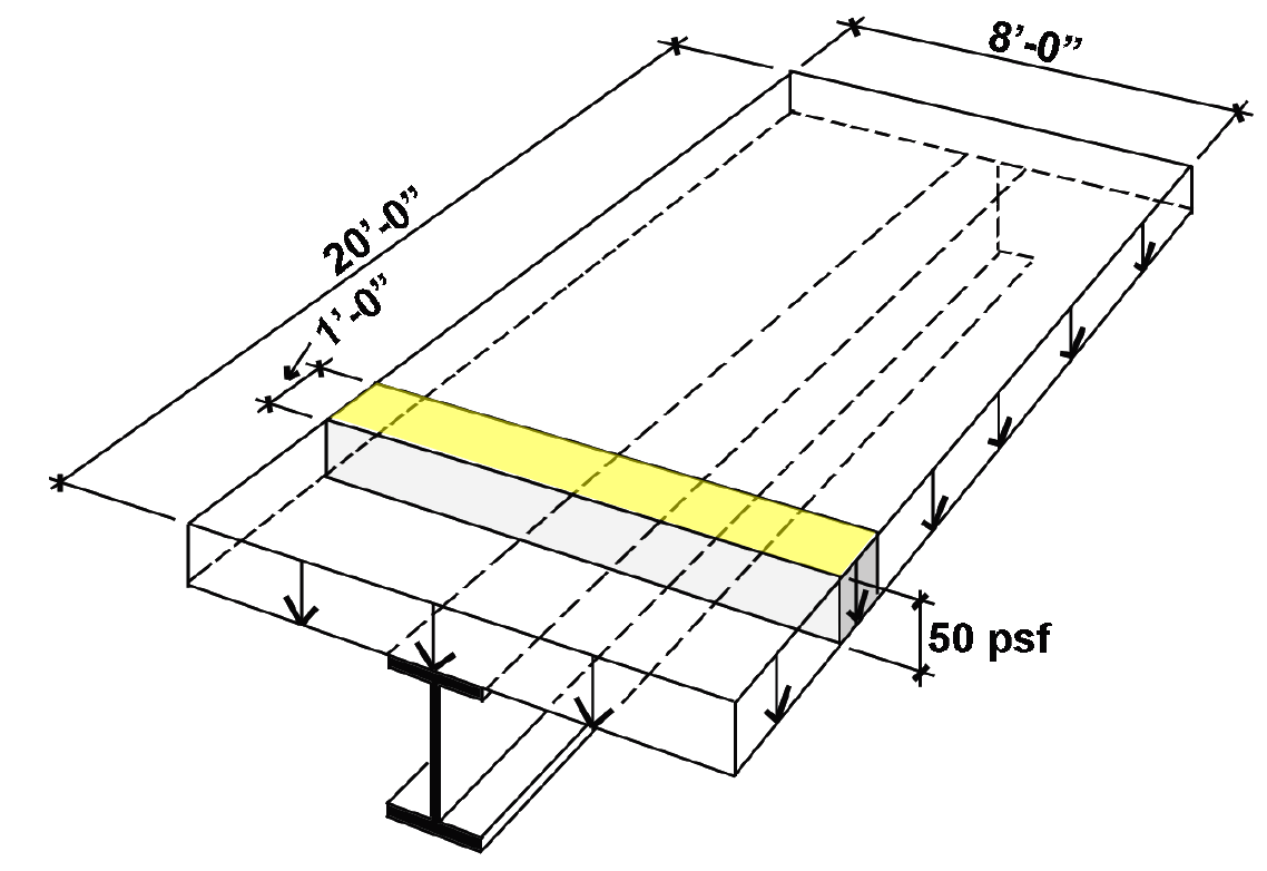
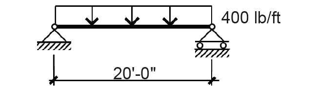
1. From Appendix Table A-2.2, the unreduced live load for office occupancy = 50 psf. The load on a linear foot of the beam, found by multiplying the unit load by the tributary area on 1 linear foot of the beam, is 50(8) = 400 lb/ft (as shown in the shaded region of Figure 2.7).
2. From Appendix Table A-2.2, consider live load reduction, based on the beam's tributary area, AT = 8 × 20 = 160 ft2 and a live load element factor, KLL = 2. Since KLLAT = 2(160) = 320 ft2 ≤ 400 ft2, no reduction is allowed, and the loading diagram remains as shown in Figure 2.8.
Girder B
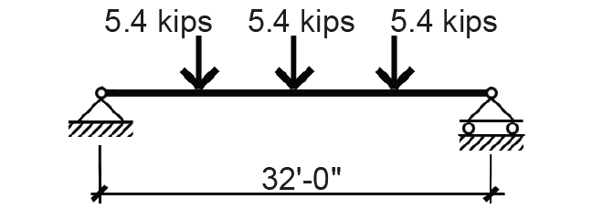
1. Find the unreduced live load on the girder, applied at the quarter-points by the reactions of the beams, each of which equals the unit load on the beam times its span divided by two, or 400(20)/2 = 4000 lb. Since two beams frame into the girder at each point, the unreduced live load is 4000(2) = 8000 lb at each of the quarter-points.
2. Consider live load reduction:
a. Find KLLAT = 2(20 × 32) = 1280 ft2. The tributary area is taken as 20 ft × 32 ft rather than 20 ft × 24 ft since the loads placed outside the middle 24 ft will have a structural effect on the girder.
b. From Equation 2.1, apply a reduction coefficient of: 0.25 + 15/![]() = 0.67. The concentrated live loads at each quarter-point become: 0.67 × 8000 = 5354 lb = 5.4 kips as shown in Figure 2.9.
= 0.67. The concentrated live loads at each quarter-point become: 0.67 × 8000 = 5354 lb = 5.4 kips as shown in Figure 2.9.
Column C, 1st floor
1. Find the unreduced live load on the column: Since the 1st-floor column of a 6-story building supports 5 floors (not including the roof), and the tributary area of each floor is 32 × 20 = 640 ft2, the total tributary area supported by the column is 5 × 640 = 3200 ft2. This results in an unreduced live load of 50 × 3200 = 160,000 lb.
2. Consider live load reduction:
a. Find KLLAT = 4(3200) = 12,800 ft2.
b. From Equation 2.1, apply a reduction coefficient of: 0.25 + 15/ = 0.38. Since the minimum reduction coefficient for columns supporting more than one level is 0.4, we use a total live load of 0.4(160,000) = 64,000 lb = 64 kips.
© 2020 Jonathan Ochshorn; all rights reserved. This section first posted November 15, 2020; last updated November 15, 2020.