
Contents | 1. Introduction to structural design | 2. Loads | 3. Wood | 4. Steel |
Introduction to reinforced concrete | Material properties | Sectional properties | Design approaches | Construction systems | Tension elements | Columns |
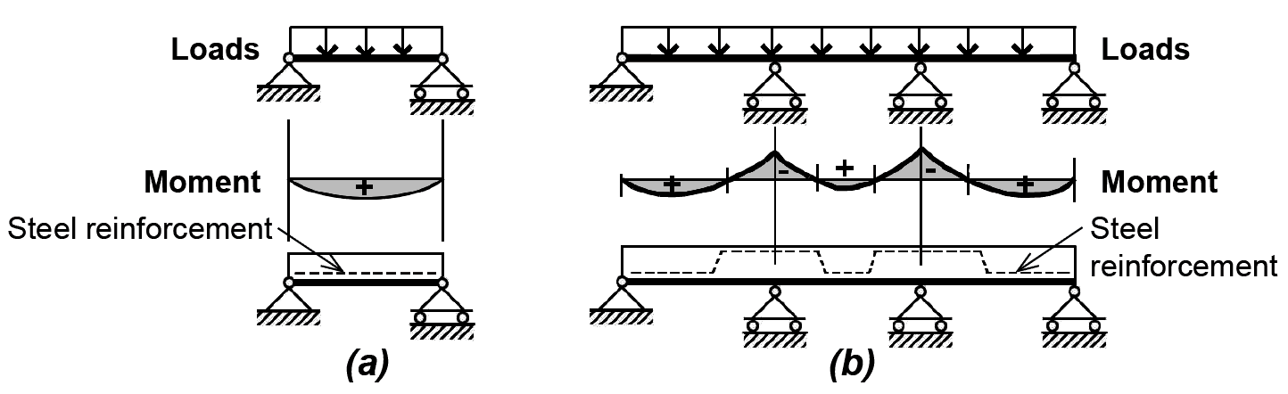
Concrete beams are reinforced with steel rods (reinforcing bars) in order to resist internal tension forces within the cross section. Unlike wood and steel, which can withstand substantial tension stress, concrete may be safely stressed only in compression. The pattern of steel reinforcement thus corresponds to the pattern of positive and negative bending moments within the beam: in regions of positive bending, steel is placed at the bottom of the cross section; in regions of negative bending, steel is placed at the top (Figure 5.21). Like concrete columns, 2½ in. to 3 in. of cover, measured from the outside face of the beam to the centerline of the reinforcing steel, is used to protect the steel from corrosion, provide fire resistance, and insure adequate bond between the steel and concrete (see Figure 5.17).
The strength, or capacity, of a reinforced concrete beam can be determined by considering the equilibrium of tensile and compressive forces at any cross section. Failure of the beam occurs either with crushing of the concrete within the compression region; or yielding of the tension steel, followed by compressive crushing of the concrete. Since tension yielding is the required mode of failure — compressive crushing of the concrete would be sudden and catastrophic, whereas yielding of the steel provides warning signs of collapse — concrete beams are deliberately under-reinforced to guarantee that, in the case of failure, the steel reinforcing bars begin to yield before the concrete in the compressive zone crushes.
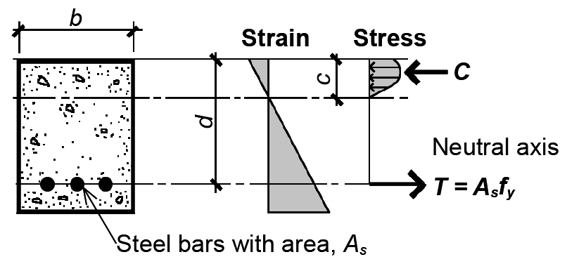
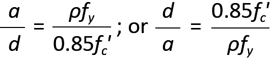
At the point of failure, the stresses in a reinforced concrete cross section are as shown in Figure 5.22. The curved distribution of stresses within the compressive zone (above the neutral axis for "positive" bending) corresponds to the nonlinear stress-strain curves characteristic of plain concrete, with a value of 0.85fc' taken for the strength of concrete corresponding to its behavior in an actual structure (Figure 5.19, curve b).
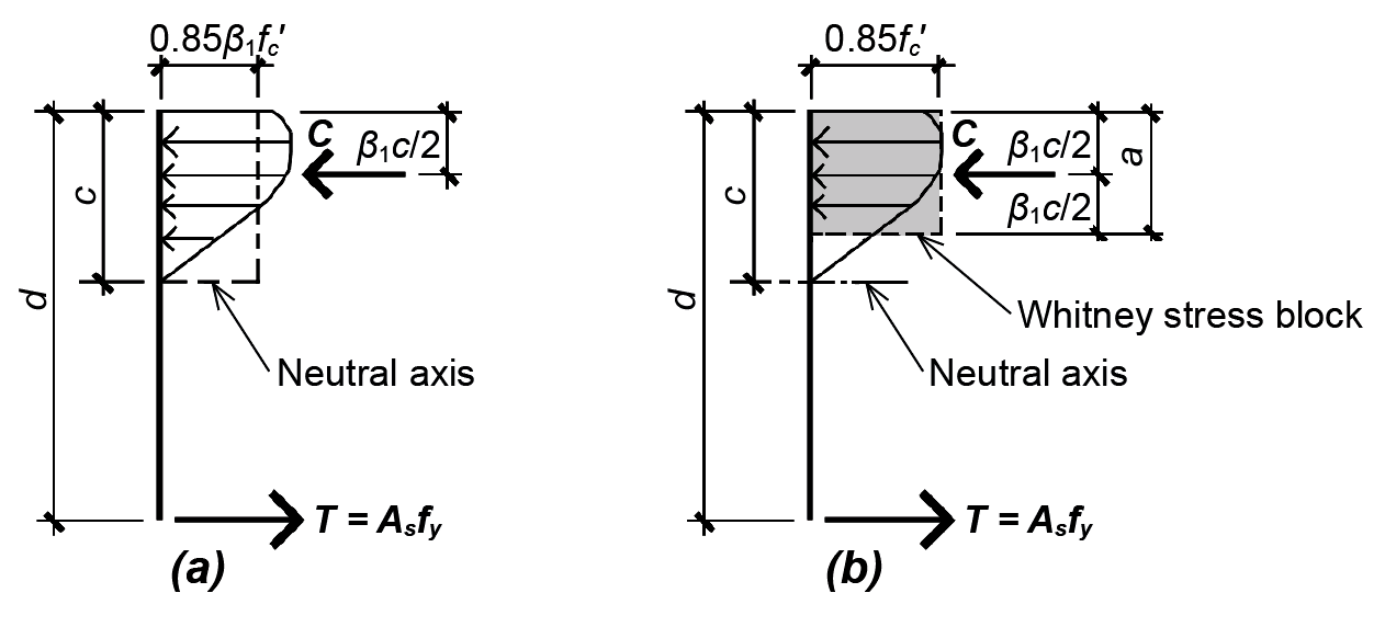
Testing of many reinforced concrete beams has shown that the average stress within the compressive zone is 0.85β1 fc', and the resultant location is β1 c/2 from the face of the concrete beam, as shown in Figure 5.23a.
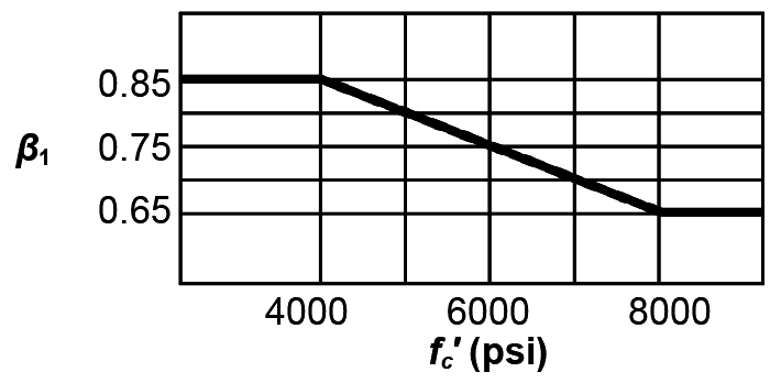
The coefficient β1 ranges from 0.85 for fc' ≤ 4000 psi, to 0.65 for fc' ≥ 8000 psi (Figure 5.24).
Thus, for a cross section of width, b, the total compressive force, C, is
Since the steel yields before the concrete crushes (assuming that the beam has been designed to be under-reinforced), the steel stress is fy and the total tensile force, T, is:
where As is the steel area. (As the steel is now used in the context of concrete design, the designation for its yield stress changes from Fy to fy.)
Alternatively, a different, but equivalent, rectangular stress distribution can be used in place of the actual nonlinear distribution, as shown in Figure 5.23b. In this version, first formulated by C. S. Whitney and known as the "Whitney stress block," the dimensions of the rectangle are adjusted so as to be consistent with the empirically-determined resultant location. The definition of β1 remains the same, as does the total compressive force, C.
Referring to the Whitney stress block diagram in Figure 5.23b, we can write equations of horizontal and moment equilibrium to determine the section's capacity. From horizontal equilibrium, the resultants of the compressive and tensile stresses must be equal in magnitude; that is: T = C, or:
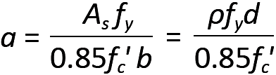
Solving for the stress block depth, a, we get:
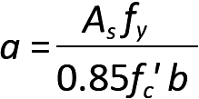
From moment equilibrium, the resisting moment within the cross section must equal the force T (or C) times the moment arm between T and C. This moment arm equals d – a/2, so we can write the moment at failure, Mn = T(moment arm); or:
Substituting the expression for a from Equation 5.7, we get:
We define a steel ratio, ρ = As /(bd), so that
Then, substituting this expression for As into Equation (5.9), we get:
This moment represents the nominal strength of the cross section when it fails. In the strength design method used for the design of reinforced concrete elements, we reduce this moment by a strength reduction factor, φ, so that the useful capacity of the section becomes:
where
φ = capacity reduction factor, 0.9 for bending
Mn = the nominal strength of the cross section (in-kips)
Mu = the "design moment" based on factored loads (in-kips)
b = the width of the cross section (in.)
d = the effective depth of the cross section measured to the centerline of the steel reinforcement (in.)
R is "assembled" from terms in Equation 5.11 and defined in Equation 5.13, as follows:
where
fy = the yield stress of the steel reinforcement (we will use 60 ksi in all examples)
fc' = the compressive cylinder strength of the concrete (ksi)
ρ = the steel ratio, As /(bd)
For given values of fy and fc', the relationship between R and ρ can be computed from Equation 5.13. Appendix Table A-5.9 gives typical values of R and ρ for fy = 60 ksi, and fc' ranging from 3000 psi to 5000 psi. Requirements for reinforcing bar cover and typical overall dimensions are the same as for reinforced concrete columns (see Appendix Table A-5.1).
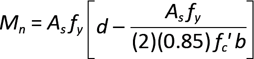
Problem definition. Check the capacity of the reinforced concrete cross section shown in Figure 5.25. Can it be safely used for the "service" (that is, unfactored) live load shown in Figure 5.25? Assume that the dead load, D, equals only the weight of the beam (assume 150 pcf for reinforced concrete, neglecting any other dead load); fy = 60 ksi; and fc' = 3000 psi. Reinforcing steel areas are listed in Appendix Table A-5.2; for minimum beam widths consistent with the number of bars selected, see Appendix Table A-5.3.
Solution overview. Find factored loads and maximum moment; compute bending capacity.
Problem solution
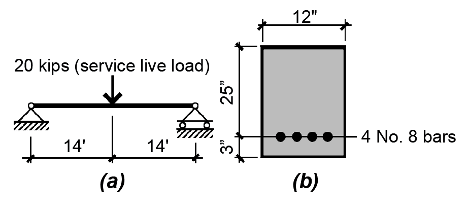
1. From Appendix Table A-2.7, the typical factored load combination for a floor beam is 1.2D + 1.6L. The factored dead load consists of 1.2 times the beam weight, and is expressed in weight per linear foot of beam: D = 1.2(150)(12/12)(28/12) = 420 lb/ft = 0.42 kips/ft. The factored live load, L = 1.6(20) = 32 kips.
2. Create load and moment diagrams as shown in Figure 5.26 to determine critical (i.e., maximum) bending moment. One can find the maximum moment for the concentrated and distributed loads separately, and then add them together (since they both occur at the beam's midpoint); or, as is shown in Figure 5.26b, the maximum moment may be computed directly by applying the equation of moment equilibrium to a free-body diagram cut at midspan.
3. Compute (bending) capacity of beam:
From Appendix Table A-5.5, φ = 0.9 for bending.
From Appendix Table A-5.2, the area of four No. 8 bars is As = 3.16 in2.
The steel ratio, ρ = As /(bd) = 3.16/(12 × 25) = 0.0105.
From Appendix Table A-5.9 or from Equation 5.13, R = 0.552 ksi (this is obtained directly from Equation 5.13; when using Appendix Table A-5.9, interpolate between values for ρ, or, conservatively, use the closest but smaller value of ρ to find R).
From Equation 5.12, φMn = φbd2R = 0.9(12)(252)(0.552) = 3726 in-kips
4. Check actual design moment: since the actual design moment = 3098 in-kips ≤ φMn = 3726 in-kips (the available moment capacity of the beam), the section is OK for bending.
For simply-supported, determinate beams, no special guidelines are required for the calculation of shear and moment. In reality, though, reinforced concrete beams are rarely simply supported. Instead, concrete floor and roof structures are most often cast monolithically, and designed as indeterminate, continuous structures. As an aid in computing the maximum negative and positive bending moments characteristic of such structures (e.g., see Figure 1.61), approximate "moment values" have been tabulated for various support conditions. These can be used for uniformly-loaded floor structures with at least two more-or-less equal spans (differing in length by no more than 20%), as long as the dead load is greater or equal to one third of the live load (Appendix Table A-5.7).
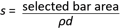
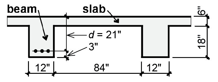
Where slabs are cast monolithically with beams, as is most often the case (the use of precast elements being the most common exception), the beam thickness is measured to the top of the slab, as shown in Figure 5.27a.

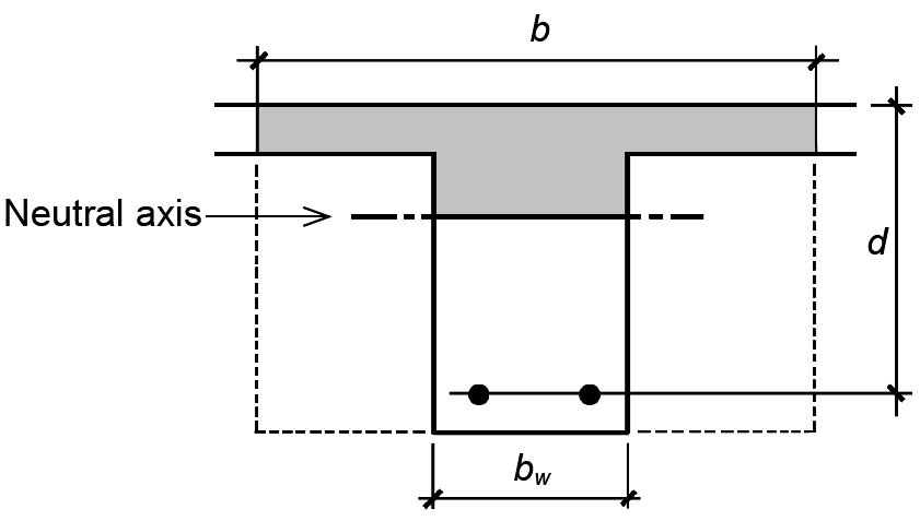
Where negative moments are being computed, corresponding to tension at the top, the beam width is not influenced by the presence of the slab (which is entirely in tension) and the capacity of the cross section is equivalent to that of a "pure" rectangular shape, as shown in Figure 5.27b. With positive bending, however, the compression zone is not limited by the web or stem of the beam, but extends out into the slab, as shown in Figure 5.27c. The effective width, b, of such a T-beam is considered to be the smaller of the following:
Positive moments can thus be resisted with a much greater effective cross-sectional width than can negative moments, by taking advantage of the concrete already present within the slab. As long as the entire compression zone (or the equivalent stress block depth, a) is within the slab, the design of such a "T-beam" is quite similar to the design of a rectangular beam of width, b. Whether the compressive stress block is, in fact, within the slab can be checked by computing the stress block depth, a (from Equation 5.7), substituting ρ = As /(bd), and comparing a to the slab thickness, as follows:
For a ≤ slab thickness, the effective beam width, b, can be used. Otherwise, the design of T-beams is somewhat more complex, since the compression zone extends into the web (Figure 5.28). The design of such beams is not considered in this text.
Where both positive and negative moments occur over the span of a beam, it is most common to first design the beam for negative moment (where only the beam web width is available to resist compression stresses), thereby establishing the cross-sectional dimensions for the entire span. The beam is then designed for positive moment as a T-beam with all cross-sectional dimensions given. Proceeding from the opposite direction, that is, positive moment first, would lead to a much smaller effective depth (since the T-beam is designed with a much larger effective width, b), which in turn could result in an inordinately high steel ratio within the regions of negative moment.
The question of whether a T-beam can be designed as a simple rectangular beam with effective width, b, is influenced to a considerable extent by the reinforcement ratio, ρ. Equation 5.15 for stress block depth shows that, for given values of fy and fc', the ratio of effective beam depth to stress block depth is inversely proportional to the steel ratio, ρ. That is, dividing both sides of Equation 5.15 by d, we get:
For the very low steel ratios characteristic of real-world positive moment T-beam design, the stress block remains within the slab thickness for all but the most extreme proportions. For example, using the steel ratio ρ = 0.000769 that we will encounter later in Example 5.7, with fy = 60 ksi and fc' = 5 ksi, the ratio d/a (from Equation 5.16) would be 92. In other words, with an effective depth, d = 21 in, the depth of the stress block, a, would be 21/92, or slightly less than ¼ in. Clearly, this is well within any reasonable slab thickness—which in this example happens to be 6 in.—so that the assumption that T-beams can be designed as simple rectangular beams is confirmed.
To create under-reinforced beams, where yielding of the tension steel precedes crushing of the concrete in the event of failure, current code guidelines stipulate that the strain in the reinforcing steel be no less than 0.005. This results in so-called tension-controlled members, allowing a simple and uniform strength reduction factor, φ = 0.9. A tension-controlled steel strain of 0.005 is far greater than 0.002, the strain at which 60 ksi steel yields — a number found by dividing this yield stress (60 ksi) by the modulus of elasticity (29,000 ksi) — thus providing a safety factor guaranteeing that the steel has already yielded when the concrete begins to crush.
The maximum steel ratio (ρmax), derived from the lowest permissible steel strain of 0.005, sets an upper limit for the amount of steel in a reinforced concrete beam where failure, should it occur, is initiated by yielding of the tensile reinforcement. By comparing the stress and strain diagrams for this condition (Figure 5.29), ρmax (the steel ratio corresponding to a steel strain of 0.005) can be found:
1. Equating similar triangles from the strain diagram in Figure 5.29, we get c/0.003 = d/0.008 from which c = 0.375d.
2. Substituting c = a/β1 into the equation above and solving for a, we get a = 0.375 β1 d.
3. From horizontal equilibrium, As fy = (ab)0.85fc'.
4. Substituting a = 0.375 β1d into the equation above and solving for the steel ratio, we get As / bd = ρmax = 0.31875β1 (fc' /fy).
With β1 = 0.85 for 3000 psi or 4000 psi concrete, and β1 = 0.8 for 5000 psi concrete (see Figure 5.24), values for ρmax can easily be computed, and have been tabulated in Appendix Table A-5.8. These limits can also be found in Appendix Table A-5.9, since the tabulated values of ρ end at the maximum value, which has been computed for concrete strengths of 3, 4, and 5 ksi.
For beams, a lower limit for the steel ratio (ρmin) is also prudent, and is set at the larger of 200/fy and 3![]() /fy (where fc' and fy are in psi units). A minimum slab steel ratio is set at 0.0018(h/d), consistent with slab requirements for minimum temperature and shrinkage reinforcement perpendicular to the direction of span, where h is the slab thickness and d is the effective depth. These lower bounds protect against a type of sudden failure that might otherwise occur in very lightly reinforced beams if the redistribution of stresses brought about by the initial cracking of concrete in the tension zone exceeds the capacity of the "cracked" cross section assumed in the calculation of steel area. For beams with relatively light loads, where even the minimum amount of steel provides greater capacity than required, it is permitted to reduce the amount of steel below the "minimum steel" limits, as
long as the area of steel provided is at least one-third larger than what would otherwise be required
by analysis. Typical minimum and maximum values for the steel ratio, ρ, are shown in Appendix Table
A-5.8 and A-5.9.
/fy (where fc' and fy are in psi units). A minimum slab steel ratio is set at 0.0018(h/d), consistent with slab requirements for minimum temperature and shrinkage reinforcement perpendicular to the direction of span, where h is the slab thickness and d is the effective depth. These lower bounds protect against a type of sudden failure that might otherwise occur in very lightly reinforced beams if the redistribution of stresses brought about by the initial cracking of concrete in the tension zone exceeds the capacity of the "cracked" cross section assumed in the calculation of steel area. For beams with relatively light loads, where even the minimum amount of steel provides greater capacity than required, it is permitted to reduce the amount of steel below the "minimum steel" limits, as
long as the area of steel provided is at least one-third larger than what would otherwise be required
by analysis. Typical minimum and maximum values for the steel ratio, ρ, are shown in Appendix Table
A-5.8 and A-5.9.
There is a subtle, but important, difference between positive-moment T-beam design (with effective "flange" width, b, and web or stem width, bw) and rectangular beam design (with constant width, b): the minimum steel ratio, ρmin, is much lower for the T-beam when expressed in terms of width, b. This is because ρmin, derived from a consideration of the beam's moment capacity before tensile cracking of the concrete, is defined in terms of the beam "web" width in the tension zone, bw, and not the effective "flange" width, b. When using steel ratios expressed in terms of the effective width, b, the minimum steel ratio values computed with bw must be divided by the ratio b/bw. To account for these lower minimum steel ratios in T-beam design, the R-ρ table provided (Appendix Table A-5.9) includes additional steel ratio values below those that would ordinarily be listed for rectangular beam design. Depending on the ratio of the effective width, b, to the web width, bw, the minimum steel ratio, written in terms of b, can easily be determined; and the design can proceed as it would for a rectangular cross section.
It is permissible to design minimum steel areas for T-beams subjected to negative bending as if they were rectangular beams with b = bw in spite of the large area of concrete in the tension flange that could, in fact, sustain a much larger "uncracked" moment. The reason for this appears to have something to do with the redundancy of continuous (indeterminate) T-beam floor systems: redistribution of moments from supports to midspan is possible if failure at the negative-moment supports renders them incapable of sustaining bending stress, essentially turning the system into a series of simply-supported spans with positive moment only. This logic does not apply in the following two situations. First, for statically determinate T-beams (such as precast cantilevered tees) where redistribution of moments is not possible, the minimum negative steel is calculated based on the flange width or twice the web (stem) width, whichever is smaller (see Appendix Table A-5.9d). Second, for any other negative moment where a T-beam cantilever occurs (i.e., where moment redistribution cannot occur), the minimum steel should be increased as it is for determinate T-beams.
Reinforced concrete beams can be safely designed within a range of sizes bracketed by these minimum and maximum steel ratios. Using ρmax results in the smallest under-reinforced cross section; while ρmin corresponds to the largest. Unlike wood and steel design, where the smallest, or lightest, cross section can usually be taken as the most economical, the best choice for a reinforced concrete beam is not necessarily the smallest cross section: the higher cost of steel relative to concrete, the potential difficulty of placing many steel reinforcing bars within a small cross-sectional area, and the reduced stiffness of a smaller cross section often suggest some intermediate steel ratio as the best choice. For example, steel ratios in the range of 0.5ρmax seem to produce reasonably proportioned beams.
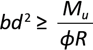
If the design of a reinforced concrete beam starts with the selection of a steel ratio, such as 0.5ρmax, we can solve for bd2 in Equation 5.12 to get:
where
b = the width (in.) of the cross section
d = the effective depth (in.) of the cross section
Mu = the design moment found using factored loads (in-kips)
φ = 0.9 for bending
R = ρfy (1 - 0.5882ρfy /fc'), as defined in Equation 5.13 (ksi units; values can also be found in Appendix Table A-5.9)
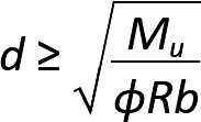
While any values of width, b, and effective depth, d, consistent with the above equation are acceptable in principle, these cross-sectional dimensions are often constrained by three practical considerations. First, beam widths must be consistent with requirements for clear space between reinforcing bars and for concrete cover, as shown in Appendix Table A-5.3. Second, beam widths and depths are often made to align with other structural elements, such as column cross sections, other beams, or different sections of the same beam. Third, the actual depth of the cross section may be chosen to prevent excessive deflection, as indicated in Appendix Table A-5.13. It can be seen that one, but not both, of the cross-sectional dimensions must be assumed before the other dimension can be found. If the effective depth, d, is assumed as given, then:
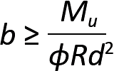
If the width, b, is assumed as given, then:
Given a steel ratio, and knowing both cross-sectional beam dimensions, the required steel area can then be found from Equation 5.10 — that is, As = ρbd.
Where both cross-sectional dimensions b and d are assumed as given, the steel ratio cannot also be selected, but must be calculated. From Equation 5.19, we found that: bd2 ≥ Mu/(φR). We can find the steel ratio, ρ, by first solving for R as follows:
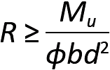
Then, the corresponding steel ratio can be determined from Appendix Table A-5.9. If the value of R does not appear in the table, two things are possible. Either the value is too low, corresponding to a required steel ratio, ρ < ρmin; or the value is too high, corresponding to a required steel ratio, ρ > ρmax. In the latter case, the cross-sectional dimensions must be changed and R recomputed. Where ρ < ρmin, one can either adjust the cross-sectional dimensions, or simply use the larger quantity of steel corresponding to ρmin. Alternatively, an acceptable steel ratio can be assumed, along with one cross-sectional dimension, and the procedures outlined earlier for "steel ratio given" can be followed.
Reinforced concrete slabs, at least those designed to span in one direction, are no different conceptually from any other beams, with the following four caveats. First, only ¾ in. concrete cover is required (see Appendix Table A-5.1), so that the effective depth, d, measured to the centerline of the reinforcing steel, can generally be taken as the slab thickness minus one inch. Second, special shear reinforcement is rarely needed. Third, rather than computing the steel area for a slab, the required spacing of reinforcing bars is computed based on an assumed steel bar area. Finally, the minimum steel area is based on the gross slab dimensions (using the thickness, h, instead of the effective depth, d), so the minimum steel area, As,min = 0.0018(h × s), where s is the slab rebar spacing, and the minimum steel ratio, ρmin = 0.00180(h/d).
The calculation of rebar spacing for a one-way slab is facilitated by considering a typical 12-in.-wide strip of slab. Just as for a beam, the design moment, Mu, is found (or moment values are used), and R is computed based on Equation 5.22, with b set equal to 12 in. From Appendix Table A-5.9, ρ is found, and the required steel area for this 12-in. strip is computed just as for a beam: As = ρbd (where b = 12 in.). At this point, the design method for slabs diverges from that for beams, since the required steel area for a 12-in. wide strip is not, in itself, a useful piece of information. Instead, we prefer to find the required spacing for a selected rebar size, often choosing a No. 3, No. 4, or No. 5 bar size with a cross-sectional area of 0.11 in2, 0.20 in2, or 0.31 in2 respectively (see Appendix Table A-5.2). Since the ratio of steel area per width of slab is now known (As /12 in.), we can establish the required width of slab — i.e., the required bar spacing — for any steel area. For example, choosing a No. 3 bar, we can equate the ratio of As /12 in. to the ratio of the No. 3 bar area to its required spacing, s: As /12 in. = 0.11/s, as shown in Figure 5.30. If a No. 4 bar were selected, the equation would be: As /12 in. = 0.20/s; for a No. 5 bar size, the equation would be As /12 in. = 0.31/s. For any of these cases, we solve for the spacing, s = 12 × (selected bar area)/As.
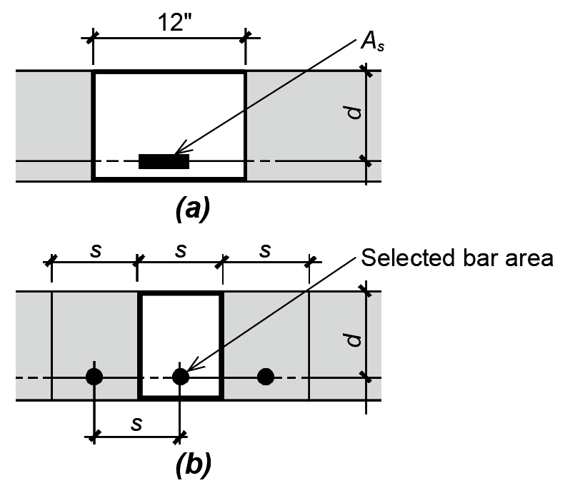
This reinforcement spacing can alternatively be determined more directly by substituting ρbd for As (where b = 12 in.) in this last equation. Doing so, we get: s = 12 × (selected bar area)/(12ρd), or:
where the "selected bar area" is typically that of a No. 3, No. 4, or No. 5 bar, and
s = the centerline spacing between bars
ρ = the computed steel reinforcing ratio
d = the effective slab depth
The spacing, s, must not exceed 18 in. nor 3 times the slab thickness, in any case. It is also common practice to choose a bar size so that the bar spacing ends up being at least 1½ times greater than the slab thickness; bars that are more closely spaced may satisfy "code" requirements, but end up being more costly to put in place.
Reinforcement may be required perpendicular to the main longitudinal slab reinforcement (i.e., perpendicular to the reinforcement placed parallel to the span) for two reasons. First, a minimum amount of perpendicular steel — with minimum steel area, As,min = 0.0018(h × s) — is required to protect against cracking due to shrinkage of the concrete or thermal (temperature) expansion. The spacing of such shrinkage-temperature steel cannot exceed 18 in. or 5h, where h is the slab thickness. Second, in cases where a T-beam is oriented so that it is parallel to the main slab reinforcement (for example, where a T-beam girder is supporting T-beams that in turn are supporting slabs, as shown in Figure 5.31), the overhanging flanges of the T-beam girder must be reinforced as if they were negative-moment cantilevers, with a design moment, Mu = wu(b – bw)2/8. This reinforcement is not designed to improve the spanning capability of the slab itself, but rather to ensure that the effective width of the T-beam can function as assumed.
The rigorous calculation of reinforced concrete beam or slab deflection is complicated by the difficulty of determining the stiffness, EI, of such bending elements that would be required in any deflection equation: in particular, the moment of inertia of a cracked section (cracked in the tension zone) containing two very different types of materials (steel and concrete) is complex and uncertain. While such procedures exist, we can control deflection — for preliminary design — by establishing minimum thicknesses for beam and slab elements based on their clear span, as shown in Appendix Table A-5.13. For example, the minimum thickness for a continuous reinforced concrete beam is set equal to its clear span divided by 21; while the minimum thickness for a continuous slab is set equal to its clear span divided by 28.
Problem definition. Assuming a steel ratio, ρ = 0.5ρmax, design a continuous rectangular concrete beam with a clear span of 36 ft to resist a positive design moment, Mu = 350 ft-kips. Assume fy = 60 ksi; and fc' = 3000 psi. The beam width is set at 16 in. to align with rectangular columns. Assume 3 in. cover, measured to the centerline of reinforcement, and use even numbers for both cross-sectional dimensions. Check thickness for deflection control.
Solution overview. Find R; compute unknown cross-sectional dimension; recompute steel ratio; compute steel area; select reinforcement.
Problem solution
1. From Appendix Table A-5.8, find steel ratio:
ρmax = 0.0135.
ρ = 0.5ρmax = 0.00675.
2. From Appendix Table A-5.9c, find R = 0.3728 based on ρ = 0.00675. Alternatively, use Equation 5.13 directly to obtain R = ρfy(1 - 0.5882ρfy/fc') = 0.00675(60)[1 - 0.5882(0.00675)(60)/3)] = 0.3728.
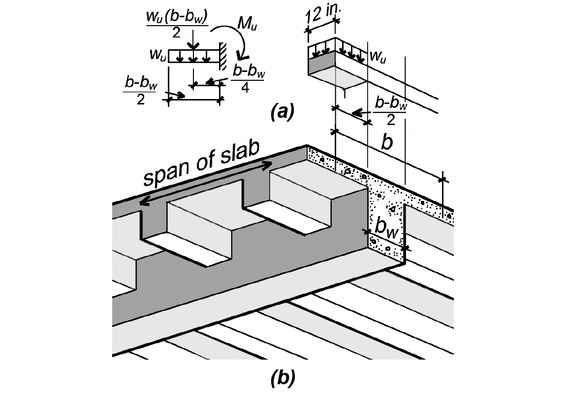
3. From Equation 5.21, compute cross-sectional dimensions: since b = 16 in., we get:
4. Adjust the effective depth, d, so that the total thickness of the cross section is an even number. Since the assumed cover is 3 in., we can select an effective depth of either 27 in. (for a total thickness of 30 in.), or an effective depth of 29 in. (for a total thickness of 32 in.). Either choice is potentially correct, since even if the depth is less than what is required based on Equation 5.21, a revised steel ratio will be computed in the next step: a smaller depth will result in a larger steel ratio (more steel and less concrete), while a larger depth will result in a smaller steel ratio (less steel and more concrete). We will choose an effective depth, d = 29 in.
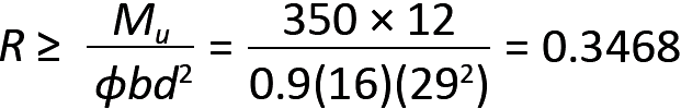
5. Find R using the actual cross-sectional dimensions, b = 16 in. and d = 29 in. From Equation 5.22, we get:
6. From Appendix Table A-5.9c, we can either use R = 0.3474 and a corresponding value of ρ = 0.00625; or we can interpolate between R = 0.3346 and R = 0.3474 to get:
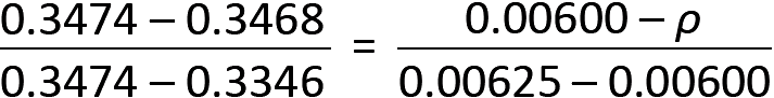
from which ρ = 0.00624. We will use the more accurate value of ρ = 0.00624. Using the value of 0.00625 would certainly work (and for preliminary design might save a few minutes of calculation time) and, at least in this case, is virtually the same.
7. From Equation 5.10, compute steel area: As = ρbd = 0.00624(16)(29) = 2.90 in2.
8. From Appendix Table A-5.2, select reinforcement that will fit in the beam, as shown in Figure 5.32: two No. 11 bars (with actual As = 3.12 in2) or three No. 9 bars (with actual As = 3.00 in2).
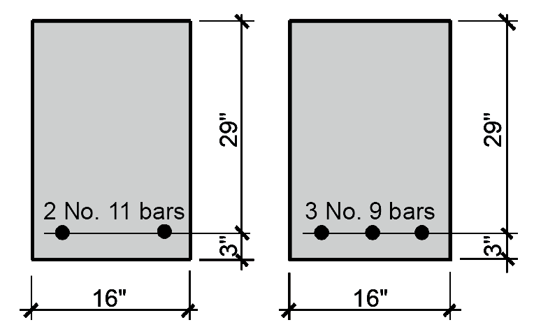
9. From Appendix Table A-5.3, check whether either choice fits within the beam width of 16 in. Two No. 11 bars require 8.13 in. and three No. 9 bars require 10.04 in., so either choice works in a 16 in.-wide beam.
10. It is unlikely that our steel ratio will fall outside the limits for ρmin and ρmax, since our starting point was the selection of a steel ratio positioned between these two extremes. However, since the actual steel ratio being used is somewhat different from what we started with, a quick check is prudent. From Appendix Table A-5.8, the range of acceptable steel ratios is 0.0033 – 0.0135. This is also the range of values shown in Appendix Table A-5.9c for 3 ksi concrete. For two No. 11 bars, the steel ratio, ρ = As /bd = 3.12/(16 × 29) = 0.0067, which falls between the two limiting values (the steel ratio for three No. 9 bars, ρ = 3.00/(16 × 29) = 0.0065, is also acceptable).
11. Check beam thickness for deflection control: from Appendix Table A-5.13, the minimum thickness for a continuous beam with clear span, L (in.), is L/21 = (36 × 12)/21 = 20.6 in. This is no greater than the actual thickness of the beam, h = d + 3 = 29 + 3 = 32 in., so the beam is acceptable for deflection control.
Problem definition. Design a continuous 6 in.-thick reinforced concrete slab supporting a live load of 100 psf (and no live load reduction) with a clear span between supports of 14 ft. Assume fy = 60 ksi; and fc' = 4000 psi. Consider both negative and positive moment values on typical interior spans (Appendix Table A-5.7). Assume that the dead load consists of the reinforced concrete weight (150 pcf). Span dimensions are measured from the inside face of supporting elements, rather than from their centerlines, when computing shear and moment. Assume a 1 in. cover for slabs (measured to centerline of reinforcement).
Solution overview. Find factored loads; compute design moment; compute R; find ρ; compute rebar spacing. Check rebar spacing and deflection control.
Problem solution
Find loads:
From Appendix Table A-2.1 (and as given in problem definition), the dead load, D = 150 pcf.
The live load is given as L = 100 psf.
Slab design, negative moment
1. Find loads on 12-in-wide strip of slab:
The live load, L = 100 psf = 100 lb/ft (for 1 linear foot of a 12-in.-wide strip of slab). Live load reduction is not being considered.
The dead load, D (for 1 linear foot of a 12-in.-wide strip of slab) = 150(6/12) = 75.0 lb/ft.
From Appendix Table A-5.4, the factored (design) load, wu = 1.2D + 1.6 L = 1.2(75) + 1.6(100) = 250 lb/ft = 0.250 kips/ft.
2. Using moment values from Appendix Table A-5.7, compute the negative design moment for a typical interior span. Because the clear span of the slab is greater than 10 ft (see Note 2, Appendix Table A-5.7), the moment value is Mu = wu ln2 /11 = 0.250 × 142/11 = 4.455 ft-kips = 53.455 in-kips. The initial calculation used kips/ft units for wu and foot units for ln, with the resulting moment value in ft-kips units. This value was then multiplied by 12 to convert the moment value to in-kips units.
3. From Equation 5.22, R ≥ Mu/(φbd2) = 53.455/(0.9 × 12 × 52) = 0.198. In this equation, the effective slab depth, d, is taken as 1 in. less than the given slab thickness, h = 6 in., consistent with typical requirements for slab cover.
4. From Appendix Table A-5.9b, we can either use R = 0.2058 and a corresponding value of ρ = 0.00354, or we can interpolate between R = 0.1939 and R = 0.2058. A value for ρ will be found by interpolation:
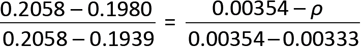
from which ρ = 0.00340.
5. From Appendix Table A-5.2, we select a value for As: assuming No. 4 reinforcing bars for the slab, As = 0.20 in2.
6. From Equation 5.23, find rebar spacing: s = As /(ρd) = 0.20/(0.00340 × 5) = 11.76 in.
The maximum permitted bar spacing for a slab is the smaller of 18 in. or three times the slab thickness, 3h = 18 in. Rounding down, negative slab moments are resisted by No. 4 bars at 11 in. on center (a value that is also greater than the "practical" minimum of 1½ times the slab thickness). In this case, the same answer would have been obtained without interpolation, using the more conservative value of ρ = 0.00354.
7. Checking the steel ratio, we find the limits from Appendix Table A-5.9b to be ρmin = 0.00180(h/d) = 0.00180(6/5) = 0.002160 (this value can also be found directly in Appendix Table A-5.9d) and ρmax = 0.01810. The actual steel ratio can be found by dividing a single bar area by the gross concrete area determined by its spacing, s, and effective depth, d:
ρ = 0.20/(11 × 5) = 0.00364, which falls between these limiting values.
8. Deflection control can be checked using Appendix Table A-5.13: for a continuous slab, the minimum thickness equals the clear span divided by 28, or (14 × 12)/28 = 6.00 in. The actual slab thickness, h = 6 in., corresponds exactly to this minimum, so the slab is thick enough for deflection control.
Slab design, positive moment
1. Find loads: same as for negative moment: wu = 0.250 kips/ft.
2. From Appendix Table A-5.7, compute the positive design moment value, Mu = wu ln2 /16 = 0.250 × 142/16 = 3.063 ft-kips = 36.75 in-kips. The initial calculation used kips/ft units for wu and foot units for ln, with the resulting moment value in ft-kips units. This value was then multiplied by 12 to convert the moment value to in-kips units.
3. From Equation 5.22, R ≥ Mu/(φbd2) = 36.75/(0.9 × 12 × 52) = 0.1361. In this equation, the effective slab depth, d, is taken as 1 in. less than the given slab thickness, h = 6 in., consistent with typical requirements for slab cover.
4. From Appendix Table A-5.9b, we can either use R = 0.1410 and a corresponding value of ρ = 0.002400, or we can interpolate between R = 0.1360 and R = 0.1410. A value for ρ will be found by interpolation:
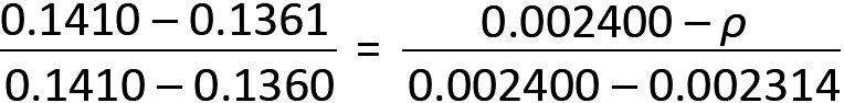
from which ρ = 0.002316.
5. From Appendix Table A-5.2, we select a value for As: assuming No. 4 reinforcing bars for the slab, As = 0.20 in2.
6. From Equation 5.23, find rebar spacing: s = As /(ρd) = 0.20/(0.002316 × 5) = 17.3 in.
The maximum permitted bar spacing for a slab is the smaller of 18 in. or three times the slab thickness, 3h = 18 in. Rounding down, negative slab moments are resisted by No. 4 bars at 17 in. on center (a value that is also greater than the "practical" minimum of 1½ times the slab thickness). In this case, the same answer would not have been obtained without interpolation, using the more conservative value of ρ = 0.002664. Instead, a more conservative spacing of 15 in. on center would have been found.
7. Checking the steel ratio, we find the limits from Appendix Table A-5.9b to be ρmin = 0.00180(h/d) = 0.00180(6/5) = 0.002160 (this value can also be found directly in Appendix Table A-5.9d) and ρmax = 0.01810. The actual steel ratio can be found by dividing a single bar area by the gross concrete area determined by its spacing, s, and effective depth, d:
ρ = 0.20/(17 × 5) = 0.00235, which falls between these limiting values.
8. Deflection control need not be checked again, as it proved acceptable in the calculations for negative steel.
Problem definition. Design a continuous reinforced concrete slab and typical beam to accommodate light manufacturing, as shown in Figure 5.33. Assume fy = 60 ksi; and fc' = 5000 psi. Consider both negative and positive moment values on typical interior spans (Appendix Table A-5.7). Assume a beam width of 12 in., and a slab thickness of 6 in. as shown. The beams have a clear span of 30 ft. Assume that the dead load consists of the reinforced concrete weight (150 pcf). Span dimensions are measured from the inside face of supporting elements, rather than from their centerlines, when computing shear and moment. Design beam and slab for typical interior spans. Assume 3-in. cover for beams, and 1 in. for slabs (measured to centerline of reinforcement).
Solution overview. For slab: find factored loads; compute design moment; compute R; find ρ; compute rebar spacing. For beam: find factored loads; compute design moment; compute R; find ρ; compute steel area, As; select reinforcement. Check bar fit for beam and deflection control for both beam and slab.
Problem solution
Find loads:
From Appendix Table A-2.1 (and as given in problem definition), the dead load, D = 150 pcf.
From Appendix Table A-2.2, the live load, L = 125 psf (light manufacturing).
Slab design, negative moment
1. Find loads on 12-in-wide strip of slab:
The live load, L = 125 psf = 125 lb/ft (for 12-in.-wide strip of slab). Live load reduction does not apply for live loads greater than 100 psf.
The dead load, D (for 12-in.-wide strip of slab) = 150(6/12) = 75.0 lb/ft (see Figure 5.34). From Appendix Table A-5.4, the factored (design) load, wu = 1.2D + 1.6L = 1.2(75) + 1.6(125) = 290 lb/ft = 0.290 kips/ft.
2. Using moment values from Appendix Table A-5.7, compute the negative design moment for a typical interior span. Because the clear span of the slab is no greater than 10 ft (see Note 2, Appendix Table A-5.7), the moment value is Mu = wu ln2 /12 = 0.290 × 72/12 = 1.184 ft-kips = 14.21 in-kips. The initial calculation used kips/ft units for wu and foot units for ln, with the resulting moment value in ft-kips units. This value was then multiplied by 12 to convert the moment value to in-kips units.
3. From Equation 5.22, R ≥ Mu/(φbd2) = 14.21/(0.9 × 12 × 52) = 0.0526. In this equation, the effective slab depth, d, is taken as 1 in. less than the given slab thickness, h = 6 in., consistent with typical requirements for slab cover.
4. From Appendix Table A-5.9a, we can either use R = 0.0528 and a corresponding value of ρ = 0.000885, or we can interpolate between R = 0.0497 and R = 0.0528. In this case, the minimum steel ratio for a slab with thickness, h = 6 in., ρmin = 0.00180(6/5) = 0.002160, so there is no point interpolating: the result — as can be seen by examining Appendix Table A-5.9a — will be less than ρmin. Therefore, we use the minimum value, ρ = 0.002160.
5. From Appendix Table A-5.2, we select a value for As: assuming No. 3 reinforcing bars for the slab, As = 0.11 in2.
6. From Equation 5.23, find rebar spacing: s = As /(ρd) = 0.11/(0.002160 × 5) = 10.19 in.
The maximum permitted bar spacing for a slab is the smaller of 18 in. or three times the slab thickness, 3h = 18 in. Rounding down, negative slab moments are resisted by No. 3 bars at 10 in. on center (a value that is also greater than the "practical" minimum of 1½ times the slab thickness).
7. Checking the steel ratio, we find the limits from Appendix Table A-5.9 to be ρmin = 0.002160 (see Appendix Table A-5.9a or A-5.9d) and ρmax = 0.02130. The actual steel ratio can be found by dividing a single bar area by the gross concrete area determined by its spacing, s, and effective depth, d:
ρ = 0.11/(10 × 5) = 0.00220, which falls between these limiting values.
8. Deflection control can be checked using Appendix Table A-5.13: for a continuous slab, the minimum thickness equals the clear span divided by 28, or (7 × 12)/28 = 3.00 in. The actual slab thickness, h = 6 in., exceeds this minimum, so the slab is thick enough for deflection control.
Slab design, positive moment
1. Find loads: same as for negative moment: wu = 0.290 kips/ft.
2. From Appendix Table A-5.7, compute the positive design moment value, Mu = wu ln2 /16. Rather than going through the computation process, notice that the positive moment is smaller than the negative moment already computed; since the negative moment in this case was governed by the minimum steel ratio, the positive moment (which is even smaller) will have the same result. Therefore, use the same bars and spacing computed for the negative moment: No. 3 bars at 10 in. on center.
Beam design, negative moment
1. Find distributed load on beam:
We found that the live load, L = 125 psf, so the distributed load per foot of beam = 125 × tributary area = 125(8) = 1000 lb/ft. Live load reduction does not apply since the live load is greater than 100 psf.
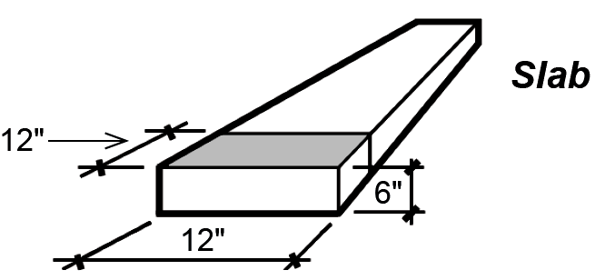
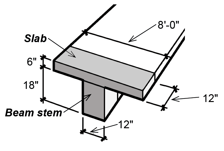
The dead load can be found by adding the slab and beam-stem weight as shown in Figure 5.35: D = slab weight + beam-stem weight = 150(6/12)(8) + 150(18/12)(12/12) = 600 + 225 = 825 lb/ft.
From Appendix Table A-5.4, the factored (design) load = 1.2D + 1.6 L = 1.2(825) + 1.6(1000) = 2590 lb/ft = 2.59 kips/ft.
2. Using moment values from Appendix Table A-5.7, compute the negative design moment for a typical interior span: Mu = wu ln2 /11 = 2.59 × 3022/11 = 211.9 ft-kips = 2542.91 in-kips.
3. From Equation 5.22, R ≥ Mu /(φbd2) = 2542.91/(0.9 × 12 × 212) = 0.5339. In this equation, the effective beam depth, d, is taken as 3 in. less than the total beam thickness, h = 24 in., measured from the bottom of the beam "web" or "stem" to the top of the slab.
4. From Appendix Table A-5.9a, we can either use R = 0.5447 and a corresponding value of ρ = 0.00975, or we can interpolate between R = 0.5318 and R = 0.5447 to get:
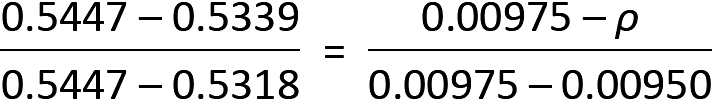
from which ρ = 0.00954. We will use the more accurate value of ρ = 0.00954.
5. From Equation 5.10, compute steel area: As = ρbd = 0.00954(12)(21) = 2.40 in2.
6. From Appendix Table A-5.2, select reinforcement that will fit in the beam, as shown in Figure 5.36: two No. 10 bars (with actual As = 2.54 in2) or three No. 9 bars (with actual As = 3.00 in2).
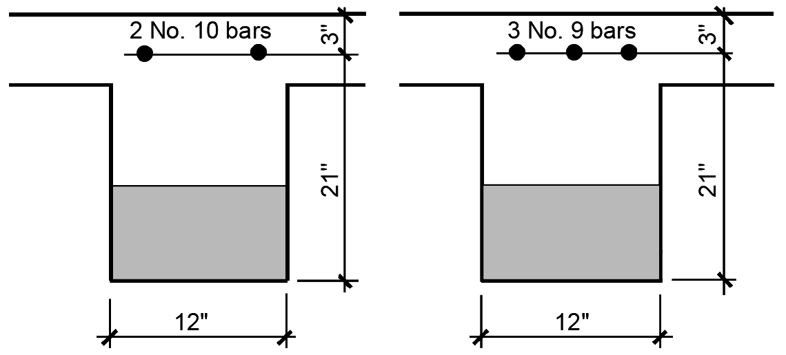
7. From Appendix Table A-5.3, check whether either choice fits within the beam web (or stem) width of 12 in. Two No. 10 bars require 7.83 in. and three No. 9 bars require 10.04 in., so either choice works in a 12-in.-wide beam.
8. Checking the steel ratio, we find the limits from Appendix Table A-5.9d to be ρmin = 0.00354 (see Appendix Table A-5.9d for negative-moment T-beams) and ρmax = 0.02130. The actual steel ratio can be found by dividing the bar area by the gross concrete area determined by width and effective depth: for the two No. 10 bars, ρ = 2.54/(12 × 21) = 0.0101, which falls between these limiting values (the steel ratio for three No. 9 bars, ρ = 3.00/(12 × 21) = 0.0119, is also acceptable).
9. Deflection control can be checked using Appendix Table A-5.13: for a continuous beam, the minimum thickness equals the clear span divided by 21, or (30 × 12)/21 = 17.14 in. The actual beam thickness, h = 24 in., is greater than this minimum, so the beam is thick enough for deflection control.
Beam design, positive moment (T-beam design)
1. Find distributed load on beam: same as for negative-moment design.
2. Using moment values from Appendix Table A-5.7, compute positive design moment for a typical interior span: Mu = wu ln2 /16 = 2.59(302)/16 = 145.69 ft-kips = 1748.3 in-kips.
3. From Equation 5.14, the effective width, b is the smaller of the following:
b = web width + 1/4 span = 12 + (30 × 12)/4 = 102 in.
b = centerline distance between beams = 96 in.
b = web width + 16 times slab thickness = 12 + (16 × 6) = 108 in.
The effective width, b = 96 in.
4. From Equation 5.22, R ≥ Mu /(φbd2) = 1748.3/(0.9 × 96 × 212) = 0.0459. In this equation, the effective beam depth, d, is taken as 3 in. less than the total beam thickness, h = 24 in., measured from the bottom of the beam web or stem to the top of the slab.
5. From Appendix Table A-5.9a, we can either use R = 0.0470 and a corresponding value of ρ = 0.000787, or we can interpolate between R = 0.0445 and R = 0.0470 to get:
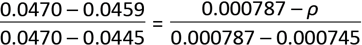
from which ρ = 0.000769. We will use the more accurate value of ρ = 0.000769.
For positive moment T-beams, the minimum steel ratio is determined by dividing 0.00354 by the ratio b/bw = 96/12 = 8, from which ρmin = 0.00354/8 = 0.000443 (see Appendix Table A-5.9a or A-5-9d). Our value of ρ is not smaller than ρmin, so it is acceptable. Because a value for ρ was actually found in Appendix Table A-5.9a (no values greater than ρmax are listed in that table) and because steel ratios for positive moment T-beams tend to be quite small, the maximum steel ratio need not be checked.
6. From Equation 5.15, check that the stress block depth, a, falls within slab thickness:
a = ρfyd /(0.85fc') = 0.000769(60)(21)/(0.85 × 5) = 0.23 in. ≤ slab thickness = 6 in., so T-beam assumptions are valid.
7. From Equation 5.10, compute steel area: As = ρbd = 0.0007697(96)(21) = 1.55 in2.
8. From Appendix Table A-5.2, steel reinforcement is selected, as shown in Figure 5.37: two No. 8 bars with As = 1.58 in2.
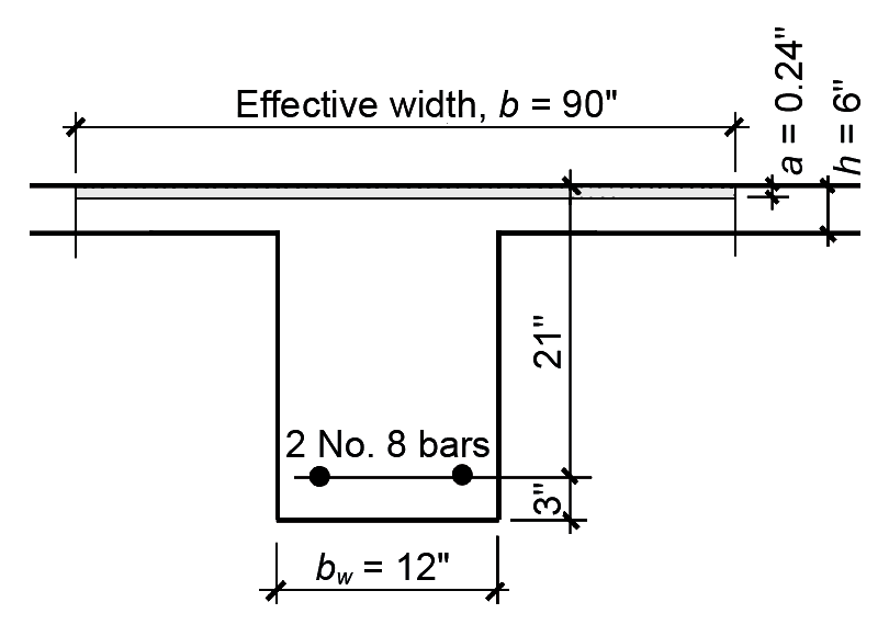
9. From Appendix Table A-5.3, check whether this choice fits within the beam web (or stem) width of bw = 12 in. Two No. 8 bars require 7.33 in., so the choice works in a 12-in.-wide beam.
10. The steel ratio has already been checked (step 5). The check for deflection control is the same as for negative moment and need not be repeated.
Wood and steel beams are generally designed for bending and checked for shear. If a beam selected for bending cannot safely resist the shear stresses, a larger section must be used. Reinforced concrete beams are almost never acceptable for shear after they are designed for bending, because shear stresses, combined with bending stresses, produce diagonal tension within the beam. Since concrete is so weak in tension, excessive shear (really diagonal tension) would cause the beam to fail catastrophically. Rather than increase the size of the cross section to the point where the concrete can safely resist all diagonal tension stresses, shear (web) reinforcement is used where the shear stress exceeds the capacity of the concrete.
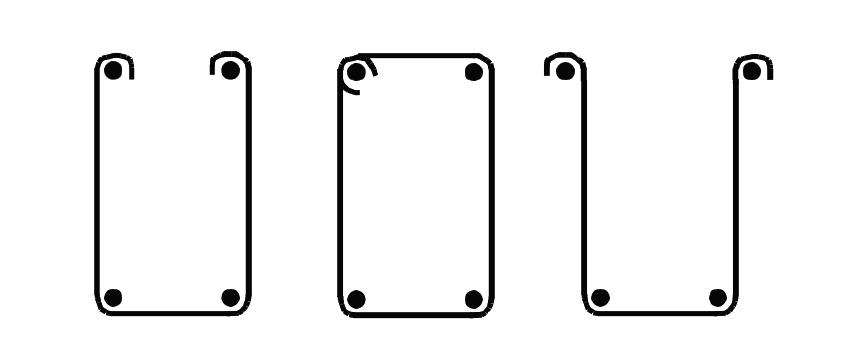
Web reinforcement, consisting of U- or rectangular-shaped steel stirrups, is generally made from No. 3 or No. 4 bars, bent as shown in Figure 5.38. The force resisted by each stirrup is based on an area twice the size of the bent bar, or Av = 2As, where As is the bar area and Av is the total area of shear reinforcement provided by a single stirrup.
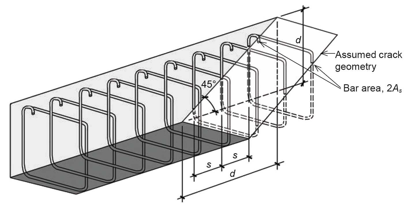
This value is double the area of the bar since two prongs of each stirrup are present at any diagonal tension crack (Figure 5.39). Thus, assuming that diagonal tension cracks form at a 45° angle, the number of stirrups resisting tension within each crack is d/s, where d = the effective depth of the beam and s = the stirrup spacing.
At failure, corresponding to yielding of the stirrups, the total force resisted by the steel web reinforcement is therefore equal to the number of stirrups times the force resisted by each; that is: Vs = (d/s)(Av fy) or:
where
Vs = the total force resisted by web reinforcement, which can be no larger than 4 × Vc (see Equation 5.26 for definition of Vc)
d = the effective depth of the beam
s = the stirrup spacing
Av = the area of shear reinforcement, equal to twice the area of the bar from which the stirrup is made
fy = the yield stress of the reinforcing bar, 60 ksi in all text examples.
Solving for the stirrup spacing, we get:
The concrete itself also inhibits the formation of diagonal tension cracks; its contribution can be taken as:
where
Vc = the total force resisted by the concrete (lb)
fc' = the cylinder strength of the concrete (psi)
b = the width of the beam, or "web" width for T-beams (in.)
d = the effective depth of the beam (in.)
The value for concrete capacity shown in Equation 5.26 presumes concrete of normal weight ("normalweight" is one word in the ACI 318 reference). For lightweight concrete, this value can be multiplied by 0.85 (sand-lightweight concrete) or 0.75 (all-lightweight concrete). This value for concrete capacity can be increased by 10 percent for 1-way joist systems, but only when they meet certain criteria governing geometry (e.g., the width of the joist "ribs" must never be less than 4 in. and the clear spacing between ribs cannot be greater than 30 in.) and continuity of reinforcement in the joists.
The strength design method for shear in concrete beams stipulates that the design shear force, Vu , at any section (produced by factored loads) not exceed the available capacity of the concrete and web steel combined. When the strength reduction factor for shear, φ, is included, we get:
where
Vu = the design shear force.
φ = capacity reduction factor = 0.75 for shear (Appendix Table A-5.5)
Vs and Vc = the values defined in Equations 5.24 and 5.26
There are several limitations that affect the deployment of web steel, as follows:
The closest practical stirrup spacing is 3 to 4 in.
The first stirrup is generally placed at a distance s/2 from the face of the support.
A minimum amount of web steel is required when Vu > 0.5φVc, even if the calculated shear force to be resisted by web steel is less than or equal to zero, i.e., for Vu ≤ φVc. This required
minimum web steel can be written in terms of a required maximum stirrup spacing: s = Av fy /(0.75b × ![]() ) ≤ Av fy /(50b). For certain beams with small total depth or thickness, this requirement is waived, in which case stirrups are only needed when Vu > φVc. Both fy and fc' are expressed in psi units; b (in.) is the beam "stem" width in this case and d is the effective depth (in.). This minimum amount of web steel is required, even if Vu < φVc; only when Vu < 0.5φVc can shear reinforcement be discontinued.
) ≤ Av fy /(50b). For certain beams with small total depth or thickness, this requirement is waived, in which case stirrups are only needed when Vu > φVc. Both fy and fc' are expressed in psi units; b (in.) is the beam "stem" width in this case and d is the effective depth (in.). This minimum amount of web steel is required, even if Vu < φVc; only when Vu < 0.5φVc can shear reinforcement be discontinued.
When Vs ≤ 2Vc, stirrup spacing cannot exceed the smaller of d/2, 24 in., or the maximum spacing governed by the requirement for minimum web steel. When Vs > 2Vc, the first two criteria are reduced by half (to the smaller of d/4 or 12 in.). Starting with ACI 318-19, limits are also placed on stirrup spacing across the beam width, perpendicular to the longitudinal direction: when Vs ≤ 2Vc, the distance between stirrup legs cannot exceed d, and when Vs > 2Vc, the distance between stirrup legs cannot exceed d/2.
A single stirrup size is used throughout a given beam; the spacing of these stirrups varies to account for changing values of shear along the span of the beam. For uniformly loaded spans, except as noted below, the maximum shear force at the face of the support is:
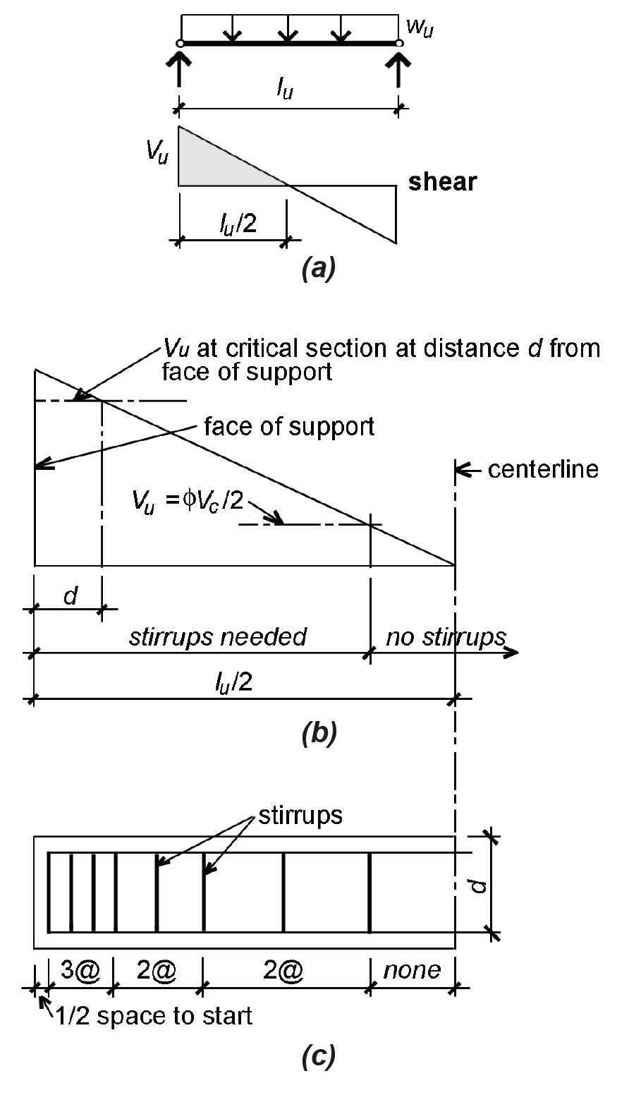
where wu is the uniformly distributed and factored design load (lb/ft or kips/ft); and lu is the clear span (ft). This applies to plan geometries with relatively equal spans and unfactored live loads that are no more than 3 times the unfactored dead loads, just as for the moment values listed in Appendix Table A-5.7. The one exception is at the "interior" support of end spans in continuous structures, for which the design shear should be taken as 1.15 times the value in Equation 5.28. Since the point of critical (maximum) shear is actually measured at a distance d from the face of the beam's support — whether that support consists of wall, column, or girder — it makes no difference if the span used in Equation 5.28 is measured from face of support or support centerline. In either case, the "theoretical" value shown in Equation 5.28 must be reduced to the value computed at the critical section. Figure 5.40b shows such a critical section measured from the face of support as well as a typical pattern of shear force and web reinforcement for a uniformly-loaded beam (Figure 5.40c). The stirrup spacing is symmetrical; only half is shown. Equations for web steel are reproduced in Appendix Table A-5.6.
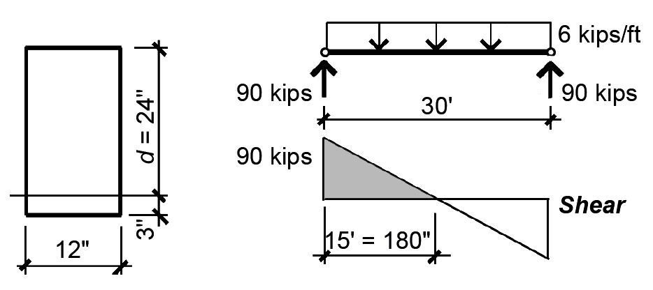
Problem definition. Design the distribution of web steel (use No. 3 bars) for the cross section shown in Figure 5.41, assuming a factored design load, wu = 6 kips/ft on a clear interior span, lu = 30 ft. Use fc' = 4000 psi and fy = 60 ksi.
Solution overview. Compute concrete capacity; find minimum, maximum and intermediate (optional) spacing for stirrups; sketch distribution of stirrups along length of beam.
Problem solution
All equations can be found in Appendix Table A-5.6 with lb or psi units; these have been converted to kips or ksi units in what follows, except where lb or psi units are specifically required (Appendix Table A-5.6 parts C and F).
1. Compute concrete shear capacity (Appendix Table A-5.6 part C):
Vc = 2bd![]() = 2(12 × 24)
= 2(12 × 24)![]() = 36,429 lbs = 36.43 kips
= 36,429 lbs = 36.43 kips
2. Find minimum spacing of No. 3 stirrups at critical Vu (at distance d from support), as shown in Figure 5.42:
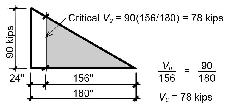
The maximum design shear at the face of support, Vu, can be taken as wu lu / 2 = 90 kips for interior spans. The design shear at the critical distance, d, from the face of support can be found using similar triangles or, more directly, by reducing the maximum value of Vu by the ratio of the small to large triangle legs, as shown in Figure 5.42: Vu at distance, d, equals 90(156/180) = 78 kips.
From Appendix Table A-5.6 part E: the steel capacity, Vs ≥ Vu /φ – Vc = 78/0.75 – 36.43 = 67.57 kips.
From Appendix Table A-5.2, the area of a No. 3 bar is As = 0.11 in2 so Av = 2As = 0.22 in2. From Appendix Table A-5.6 part B: the required spacing, s ≤ Av fy d/Vs = (0.22)(60)(24)/67.57) = 4.69 in.
Round down the required spacing to the first half-inch increment: s = 4.5 in.
3. Find maximum spacing of No. 3 stirrups:
From Appendix Table A-5.6 part F, and since Vs = 67.57 kips ≤ 2Vc = 2(36.43) = 72.86 kips, the maximum stirrup spacing is governed by the smaller of d/2 =12 in., 24 in., or the spacing corresponding to the requirement for minimum web steel: Av fy /(0.75b × ![]() ) ≤ Av fy /(50b) or 22 in. (fy and fc' must be in psi units in this equation!) The maximum spacing is therefore 12 in.
) ≤ Av fy /(50b) or 22 in. (fy and fc' must be in psi units in this equation!) The maximum spacing is therefore 12 in.
The location along the beam elevation where this maximum stirrup spacing can begin is found as follows. First find the steel capacity corresponding to the maximum spacing from Appendix Table A-5.6 part A:
Vs = Av fy d/s = (0.22)(60)(24)/12 = 26.4 kips.
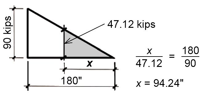
Next, find the total design shear corresponding to the steel and concrete capacities at this location from Appendix Table A-5.6 part D: Vu = φ(Vc + Vs) = 0.75(36.43 + 26.4) = 47.12 kips.
Finally, use similar triangles to determine the distance from the beam centerline corresponding to the location where maximum stirrup spacing can begin, as shown in Figure 5.43. The starting point for maximum spacing is no further than 94.24 in. from the beam centerline.
4. Find location where no stirrups are needed:
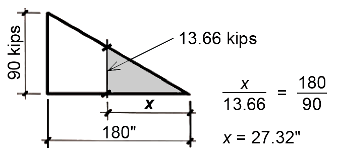
From Appendix Table A-5.6 part G, Vu = 0.5φVc = 0.5(0.75)(36.43) = 13.66 kips.
The location along the beam elevation where no stirrups are required can be found by using similar triangles, as shown in Figure 5.44. The starting point for no stirrups is no further than 27.32 in. from the beam centerline.
5. (Optional) Select intermediate spacing between minimum and maximum values determined earlier:
Choose a spacing between the smallest required at the support (4.5 in.) and the maximum (12 in.), for example, s = 8 in.
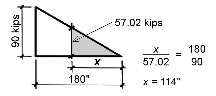
Determine starting point for intermediate spacing as follows. First, find the steel capacity corresponding to the chosen spacing: from Appendix Table A-5.6 part A, Vs = Av fy d/s = (0.22)(60)(24)/8 = 39.6 kips. Next, find the total design shear corresponding to the steel and concrete capacities at this location from Appendix Table A-5.6 part D:
Vu = φ(Vc + Vs) = 0.75(36.43 + 39.6) = 57.02 kips.
Finally, use similar triangles to determine the distance from the beam centerline corresponding to the location where this intermediate stirrup spacing can begin, as shown in Figure 5.45. The starting point for intermediate spacing, s = 8 in., is no further than 114 in. from the beam centerline.
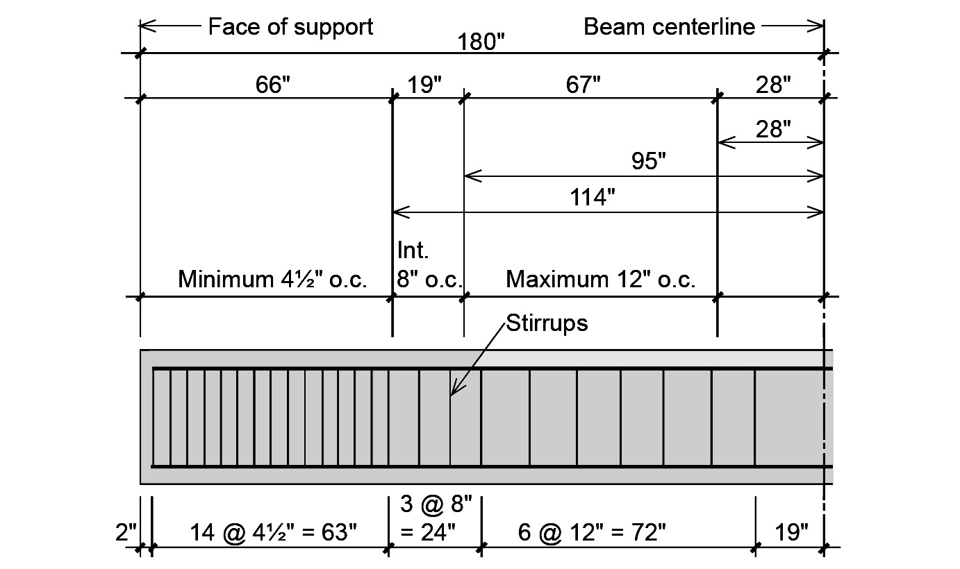
6. Sketch the distribution of web steel (stirrups) for one half of the beam. The first stirrup is generally placed at a distance s/2 = 4.5/2 = 2.25 in. from the face of the support (round down to 2 in.). The remaining stirrups are arranged within the zones of minimum, intermediate (optional) and maximum spacing, as shown in Figure 5.46. In this example, the middle 38 inches (that is, twice 19 in.) of the beam are not required to have stirrups.
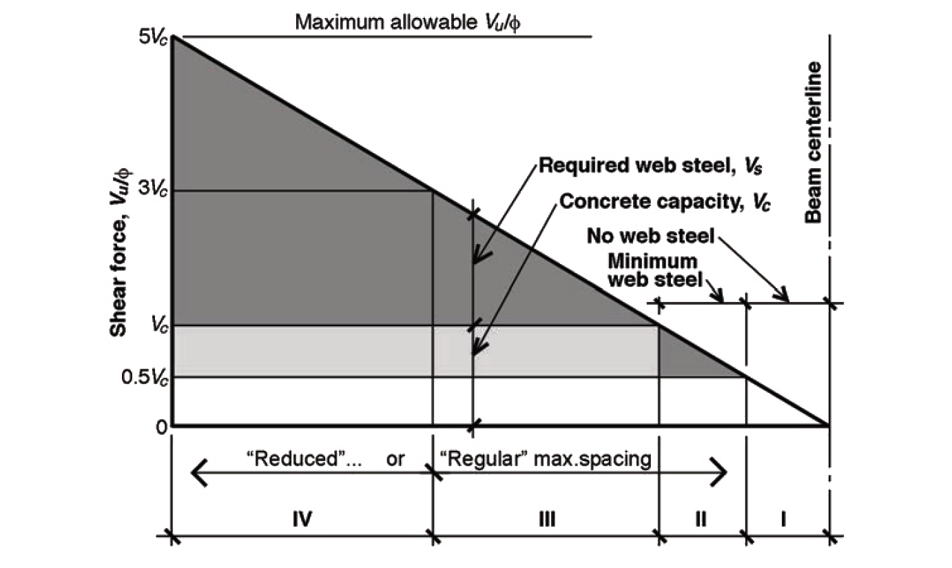
Depending on the beam's cross-sectional dimensions, span, load, and material properties, the distribution of stirrup spacing can sometimes become even more complex for uniformly loaded beams with a triangular shear force pattern. As can be seen in Figure 5.47, there are four possible zones where the maximum shear force might occur, these zones bounded by values of Vu /φ equal to 0, 0.5Vc, Vc, 3Vc , and 4Vc. These bounded areas are significant since they define four zones with different criteria for stirrup spacing. In zone I, no stirrups are needed; in zone II, only minimum web steel is needed; in zone III, stirrup spacing cannot exceed the limits of "regular" maximum spacing (the smaller of d/2, 24 in., or the value determined by minimum web steel); and in zone IV, stirrup spacing cannot exceed the limits of "reduced" maximum spacing (the smaller of d/4, 12 in., or the value determined by minimum web steel). The upper limit of 5Vc corresponds to the maximum acceptable value of Vu /φ — beyond that point, the shear force resisted by web steel is considered too high, and is not permitted.
Aside from the added cost and inefficiency of using too much steel, nothing prevents a designer from deploying stirrups at the minimum spacing, corresponding to the largest shear force, throughout the length of the beam. And there is also no prohibition against creating a greater number of spacing conditions, using any number of "intermediate" spacings, to minimize the amount of steel used in the beam. Finally, stirrup spacing over regions with constant shear force, Vu — commonly encountered in girders with concentrated loads — can be found with the same equations used in Example 5.7 and summarized in Appendix Table A-5.6.
© 2020 Jonathan Ochshorn; all rights reserved. This section first posted November 15, 2020; last updated May 28, 2024.