
Contents | 1. Introduction to structural design | 2. Loads | 3. Wood | 4. Steel |
Introduction to reinforced concrete | Material properties | Sectional properties | Design approaches | Construction systems | Tension elements | Columns | Beams | Connections |
Table A-5.1: Dimensions of reinforced concrete beams, columns, and slabs
| A. Cover requirements (from outside face of concrete to face of closest rebar) | |
|---|---|
| Interior | 1½ in. (or ¾ in. for slabs) |
| Exterior or exposed to ground | 2 in. (or 1½ in. for No.5 bars or smaller) |
| Formed directly to ground | 3 in. |
| B. Typical gross dimensions | |
|---|---|
| Beams and columns | Round to the nearest inch, or 2 in. increment, for all outside (gross) dimensions |
| Slabs | Round to ½ in. increment (or 1 in. increment if over 6 in. thick) |
Table A-5.2: Steel reinforcement — rebar — areas (in2) for groups of bars
| Designation and diameter | Number of bars | |||||||||||||||
|---|---|---|---|---|---|---|---|---|---|---|---|---|---|---|---|---|
| Bar No.1 | SI Bar No.1 | Dia. (in.) | 1 | 2 | 3 | 4 | 5 | 6 | 7 | 8 | 9 | 10 | 11 | 12 | 14 | 16 |
| 3 | 10 | 0.375 | 0.11 | No. 3 (10) bars are used primarily for ties and in slabs | ||||||||||||
| 4 | 13 | 0.500 | 0.20 | 0.40 | 0.60 | 0.80 | 1.00 | 1.20 | 1.40 | 1.60 | 1.80 | 2.00 | 2.20 | 2.40 | 2.80 | 3.20 |
| 5 | 16 | 0.625 | 0.31 | 0.62 | 0.93 | 1.24 | 1.55 | 1.86 | 2.17 | 2.48 | 2.79 | 3.10 | 3.41 | 3.72 | 4.34 | 4.96 |
| 6 | 19 | 0.750 | 0.44 | 0.88 | 1.32 | 1.76 | 2.20 | 2.64 | 3.08 | 3.52 | 3.96 | 4.40 | 4.84 | 5.28 | 6.16 | 7.04 |
| 7 | 22 | 0.875 | 0.60 | 1.20 | 1.80 | 2.40 | 3.00 | 3.60 | 4.20 | 4.80 | 5.40 | 6.00 | 6.60 | 7.20 | 8.40 | 9.60 |
| 8 | 25 | 1.000 | 0.79 | 1.58 | 2.37 | 3.16 | 3.95 | 4.74 | 5.53 | 6.32 | 7.11 | 7.90 | 8.69 | 9.48 | 11.06 | 12.64 |
| 9 | 29 | 1.128 | 1.00 | 2.00 | 3.00 | 4.00 | 5.00 | 6.00 | 7.00 | 8.00 | 9.00 | 10.00 | 11.00 | 12.00 | 14.00 | 16.00 |
| 10 | 32 | 1.270 | 1.27 | 2.54 | 3.81 | 5.08 | 6.35 | 7.62 | 8.89 | 10.16 | 11.43 | 12.70 | 13.97 | 15.24 | 17.78 | 20.32 |
| 11 | 36 | 1.410 | 1.56 | 3.12 | 4.68 | 6.24 | 7.80 | 9.36 | 10.92 | 12.48 | 14.04 | 15.60 | 17.16 | 18.72 | 21.84 | 24.96 |
| 314 | 43 | 1.693 | 2.25 | 4.50 | 6.75 | 9.00 | 11.25 | 13.50 | 15.75 | 18.00 | 20.25 | 22.50 | 24.75 | 27.00 | 31.50 | 36.00 |
| 318 | 57 | 2.257 | 4.00 | 8.00 | 12.00 | 16.00 | 20.00 | 24.00 | 28.00 | 32.00 | 36.00 | 40.00 | 44.00 | 48.00 | 56.00 | 64.00 |
Notes:
1. Rebars in the US were traditionally designated by the nominal diameter (in.) multiplied by eight, so that a No. 3 bar, for example, has a nominal diameter of ⅜ in. Rebars are no longer marked using this designation (see Note 2).
2. Rebars are currently marked by the approximate number of millimeters in their diameter (SI units), although designation by nominal diameter (in.) multiplied by eight is still widely used in the US.
3. No. 14 and No. 18 bars are used primarily in columns.
Table A-5.3: Reinforced concrete minimum width or diameter (in.) based on bar spacing
| A. Minimum width (in.) for beams3 | 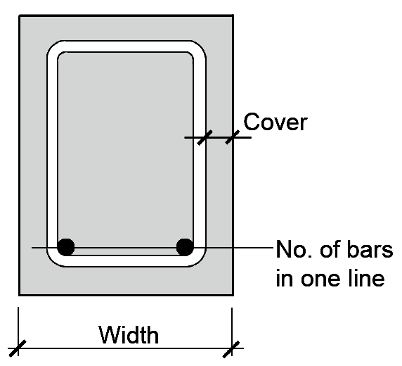 | ||||||
|---|---|---|---|---|---|---|---|
| Designation | Number of bars in one line | Bar No1 | SI Bar No2 | 2 | 3 | 4 | 5 | 6 |
| 4 | 13 | 6.33 | 8.17 | 10.00 | 11.83 | 13.67 | |
| 5 | 16 | 6.58 | 8.54 | 10.50 | 12.46 | 14.42 | |
| 6 | 19 | 6.83 | 8.92 | 11.00 | 13.08 | 15.17 | |
| 7 | 22 | 7.08 | 9.29 | 11.50 | 13.71 | 15.92 | |
| 8 | 25 | 7.33 | 9.67 | 12.00 | 14.33 | 16.67 | |
| 9 | 29 | 7.58 | 10.04 | 12.50 | 14.96 | 17.42 | |
| 10 | 32 | 7.83 | 10.42 | 13.00 | 15.58 | 18.17 | |
| 11 | 36 | 8.13 | 10.88 | 13.63 | 16.38 | 19.13 | |
| B. Minimum width (in.) for tied columns3 | 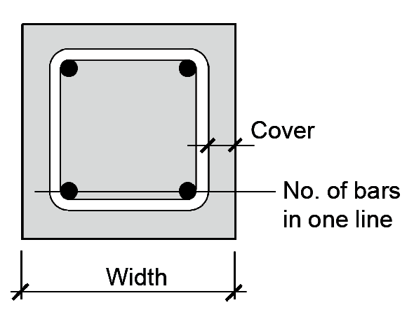 | ||||||
|---|---|---|---|---|---|---|---|
| Designation | Number of bars in one line | Bar No1 | SI Bar No2 | 2 | 3 | 4 | 5 | 6 |
| 4 | 13 | 6.50 | 8.50 | 10.50 | 12.50 | 14.50 | |
| 5 | 16 | 6.75 | 8.88 | 11.00 | 13.13 | 15.25 | |
| 6 | 19 | 7.00 | 9.25 | 11.50 | 13.75 | 16.00 | |
| 7 | 22 | 7.25 | 9.63 | 12.00 | 14.38 | 16.75 | |
| 8 | 25 | 7.50 | 10.00 | 12.50 | 15.00 | 17.50 | |
| 9 | 29 | 7.94 | 10.75 | 13.56 | 16.38 | 19.19 | |
| 10 | 32 | 8.38 | 11.50 | 14.63 | 17.75 | 20.88 | |
| 11 | 36 | 8.81 | 12.25 | 15.69 | 19.13 | 22.56 | |
| 14 | 43 | 10.13 | 14.50 | 18.88 | 23.25 | 27.63 | |
| 18 | 57 | 11.88 | 17.50 | 23.13 | 28.75 | 34.38 | |
| C. Minimum diameter (in.) for spiral columns3 | 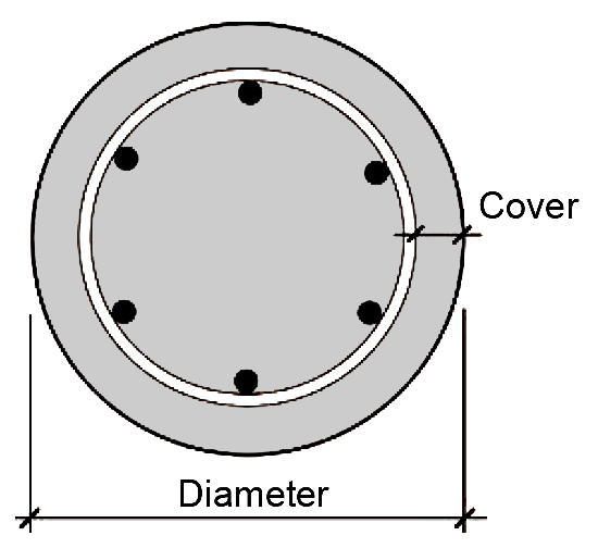 | ||||||
|---|---|---|---|---|---|---|---|
| Designation | Number of bars in one line | Bar No1 | SI Bar No2 | 6 | 8 | 10 | 12 | 14 |
| 4 | 13 | 8.50 | 9.73 | 10.97 | 12.23 | 13.49 | |
| 5 | 16 | 8.88 | 10.18 | 11.50 | 12.84 | 14.17 | |
| 6 | 19 | 9.25 | 10.63 | 12.03 | 13.44 | 14.86 | |
| 7 | 22 | 9.63 | 11.08 | 12.56 | 14.05 | 15.55 | |
| 8 | 25 | 10.00 | 11.53 | 13.09 | 14.66 | 16.23 | |
| 9 | 29 | 10.75 | 12.47 | 14.23 | 15.99 | 17.76 | |
| 10 | 32 | 11.50 | 13.42 | 15.36 | 17.32 | 19.29 | |
| 11 | 36 | 12.25 | 14.36 | 16.50 | 18.66 | 20.82 | |
| 14 | 43 | 14.50 | 17.18 | 19.91 | 22.65 | 25.41 | |
| 18 | 57 | 17.50 | 20.95 | 24.45 | 27.98 | 31.53 | |
Notes:
1. Rebars in the United States were traditionally designated by the nominal diameter (in.) divided by eight. Rebars are no longer marked using this designation.
2. Rebars are currently designated (and marked) by the approximate number of millimeters (SI units) in their diameter.
3. These minimum dimensions assume 1 in. maximum aggregate; 1½ in. cover (measured from outside face of rebar or spiral to face of concrete); and ½ in.-diameter stirrups, ties, or spiral. Minimum widths or diameters are typically rounded up to nearest inch, or to the nearest even inch. The amount of column steel is also limited by the required reinforcement ratio, ρg, between 0.01 and 0.08.
Table A-5.4: Specifications for steel ties and spirals in reinforced concrete columns
| Ties | |
|---|---|
Use minimum No. 3 bars to confine longitudinal steel up to No. 10; use
minimum No. 4 bars for No. 11, 14, and 18 longitudinal steel.
Center-to-center spacing of ties is the smaller of:
|
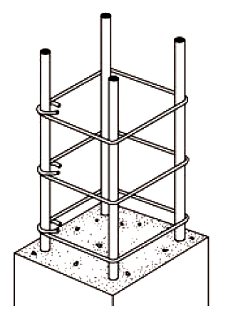 |
| Spirals | |
| Use a continuous bar or wire of at least ⅜-in. diameter, with the clear space measured between turns of the spiral no more than 3 in. and no less than 1 in or 4/3 of maximum aggregate size. A minimum ratio, ρs, of the volume of spiral steel to the volume of concrete inside the spiral (the
"core") is also specified: ρs = 0.45(Ag / Ag – 1)(fc' / fy) with fy ≤ 60 ksi, Ag being the gross concrete area, and Ac being the area of the "core" within the spiral. |
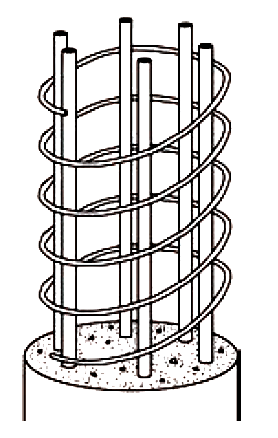 |
Table A-5.5: Reinforced concrete strength reduction factors, φ and α
| Type of behavior | φ | α1 |
|---|---|---|
| Bending | 20.9 | n/a |
| Axial tension | 0.9 | n/a |
| Axial compression: spiral columns | 30.75 | 0.85 |
| Axial compression: tied columns | 30.65 | 0.80 |
| Shear | 0.75 | n/a |
Notes:
1. α accounts for unintended eccentricity or bending moment.
2. φ decreases linearly from value listed above at εt = 0.005 to 0.65 or 0.75 (for tied or spiral lateral reinforcement respectively) at εt = 0.002, where εt is the net tensile strain in the extreme tension steel (we assume "tension-controlled" sections in this text, with values of φ = 0.9 as shown).
3. φ increases linearly from value listed above at εt = 0.002 to 0.9 at εt = 0.005, where εt is the net tensile strain in the extreme tension steel for elements with combined compression and bending (this type of combined loading is beyond the scope of this book; in the problems considered herein, with only compressive stresses, the value of φ is as shown).
Table A-5.6: "Shear" equations for reinforced concrete beams1
| Equation | |
|---|---|
| A. Capacity of steel stirrups2 (lb) | 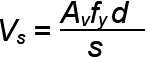 |
| B. Required stirrup spacing2 (in.) | 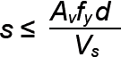 |
| C. Capacity of concrete (lb)3 | Vc = 2bd |
| D. Strength design equation2 | Vu ≤ φ(Vc + Vs) |
| E. Required steel capacity (lb) from strength design equation2 | 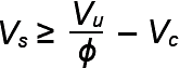 |
| F. Maximum stirrup spacing3 (in.) | For Vs ≤ 2Vc, the smaller of:
|
| G. Design shear where no stirrups are needed2 (lb) | Vu = 0.5φVc |
Notes:
1. Units are as follows:
b = cross section width, or "web" width for T-beams (in.)
d = cross section effective depth (in.)
s = stirrup spacing (in.)
Av = total stirrup bar area, equal to 2As, including both "prongs" (in2)
fy = yield stress of steel stirrup (psi)
fc' = cylinder strength of concrete (psi)
Vu = design (factored) shear force (lb)
Vc = capacity of concrete to resist shear (lb)
Vs = capacity of steel stirrups to resist shear (lb)
φ = 0.75 for shear (see Appendix Table A-5.5)
2. Pound (lb) and pound per square inch (psi) units specified according to Note 1 may be changed to kips and ksi in these equations only.
3. The concrete cylinder strength fc' must be in psi units in Appendix Table 5.6 part C (with the resulting value of Vc in lb units) and both the steel yield stress fy and the concrete cylinder strength fc' must be psi units in part F (with in. units resulting).
4. This limiting value for maximum spacing corresponds to the minimum amount of web steel required when Vu > 0.5φVc, except that it does not apply when the total beam depth (thickness, h) is less than 10 in. or, for T-beams, when the total beam depth is less than 24 in. and is also less than the larger of 2.5 × flange depth or 0.5 × the beam stem width.
Table A-5.7: Approximate moment values for continuous reinforced concrete beams and slabs1
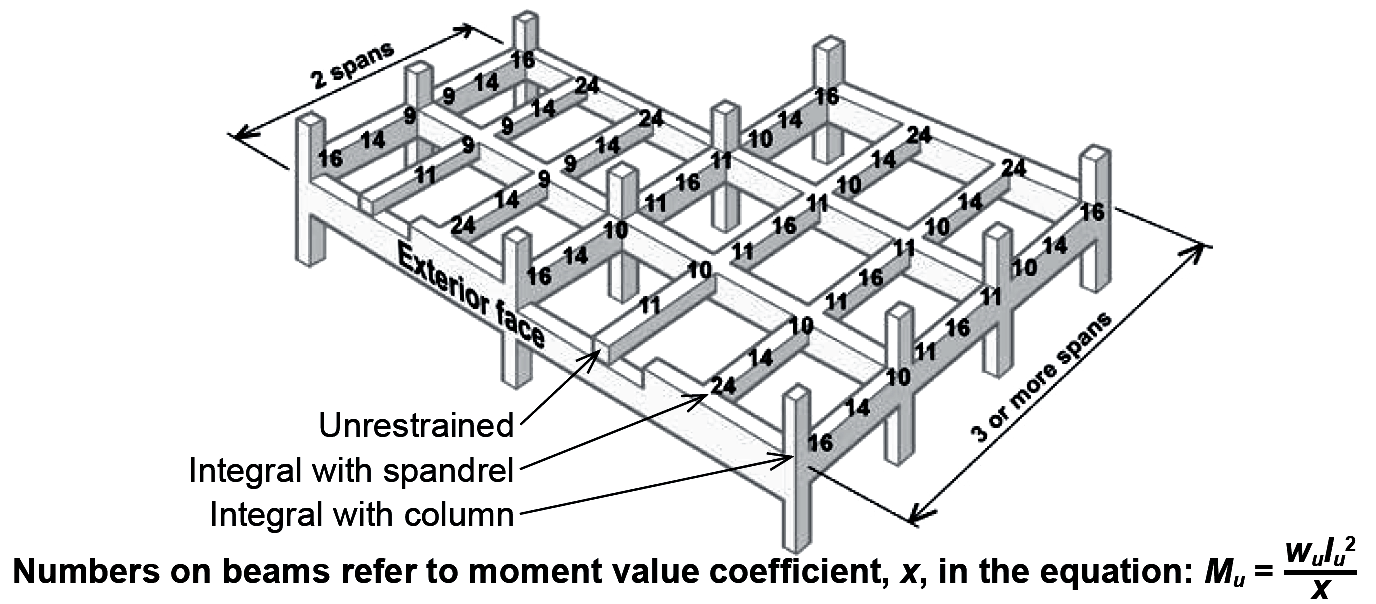 | |||||
| End restraints for two spans | Positive moment | Negative moment | |||
|---|---|---|---|---|---|
| End span | End span | ||||
| At interior support2 | At exterior support2 | ||||
| Discontinuous end unrestrained | wu ln2 / 11 | n/a | n/a | ||
| Discontinuous end restrained by spandrel girder | wu ln2 / 14 | wu ln2 / 9 | wu ln2 / 24 | ||
| Discontinuous end restrained by column | wu ln2 / 14 | wu ln2 / 9 | wu ln2 / 16 | ||
| End restraints for three or more spans | Positive moment | Negative moment | |||
| Interior span | End span | Typical interior support2 | End span | ||
| At interior support2 | At exterior support2 | ||||
| Discontinuous end unrestrained | wu ln2 / 16 | wu ln2 / 11 | n/a | n/a | n/a |
| Discontinuous end restrained by spandrel girder | wu ln2 / 16 | wu ln2 / 14 | wu ln2 / 11 | wu ln2 / 10 | wu ln2 / 24 |
| Discontinuous end restrained by column | wu ln2 / 16 | wu ln2 / 14 | wu ln2 / 11 | wu ln2 / 10 | wu ln2 / 16 |
Notes:
1. The units for uniformly distributed design load, wu, are typically lb/ft or kips/ft; the units for clear span, ln, are feet; and the resulting moment value, Mu is in ft-lb or ft-kips depending on the units chosen for the distributed load. These moment values are valid only for continuous reinforced concrete beams or slabs when the following conditions are met:
a. Lengths of adjacent spans do not differ by more than 20%.
b. The unfactored live load is less than or equal to 3 times the unfactored dead load.
2. The negative moment (at the face of support) can be taken as wu ln2 / 12 for slabs with clear spans no greater than 10 ft, and for beams framing into relatively stiff columns (specifically, the sum of column stiffness divided by the sum of beam stiffness at each end of the beam must be greater than 8). Stiffness is the product of modulus of elasticity and moment of inertia, neither of which are straightforward quantities for structural elements consisting of two materials bonded together. For normalweight concrete, the modulus of elasticity, Ec (psi), may be taken as 57,000![]() , where the cylinder strength of concrete, fc', is in psi units. The calculation of moment of inertia is left to the designer, with the American Concrete Institute (ACI) permitting any "reasonable and consistent assumptions." One suggestion is to use gross EcI values for both beams and columns. Where Ec is the same for all members, a typical joint with columns and beams at all four orthogonal points, and constant width for column and beam sections, would qualify for the wu ln2 / 12 negative beam moment only when the column thickness at that joint becomes more than twice the beam thickness.
, where the cylinder strength of concrete, fc', is in psi units. The calculation of moment of inertia is left to the designer, with the American Concrete Institute (ACI) permitting any "reasonable and consistent assumptions." One suggestion is to use gross EcI values for both beams and columns. Where Ec is the same for all members, a typical joint with columns and beams at all four orthogonal points, and constant width for column and beam sections, would qualify for the wu ln2 / 12 negative beam moment only when the column thickness at that joint becomes more than twice the beam thickness.
Table A-5.8: Limits on steel ratio for "tension-controlled" reinforced concrete beams1,2,3
| fc' (psi) | Limits on steel ratio, ρmin – ρmax |
|---|---|
| 3000 | 0.00333 – 0.01350 |
| 4000 | 0.00333 – 0.01810 |
| 5000 | 0.00354 – 0.02130 |
Notes:
1. Values are for fy = 60 ksi, φ = 0.9, and steel strain, εt = 0.005 for ρmax.
2. Values for maximum steel ratio apply to all beams and one-way slabs; values for minimum steel ratio apply only to rectangular beams and negative-moment indeterminate T-beams; the minimum steel ratio for positive moment T-beams is ρmin = 0.00333/ (b/bw) for fc' = 3000 psi and 4000 psi, and 0.00354/(b/bw) for fc' = 5000 psi; and the minimum steel ratio for one-way slabs is ρmin = 0.00180/(h/d). For details, see Appendix Table A-5.9 Part d.
3. It is permitted to reduce the amount of steel below the minimum values stipulated for beams, as long as the steel area provided is at least one-third greater than the steel area required by analysis.
Table A-5.9: Values of R and ρ for reinforced concrete beams, T-beams, and one-way slabs (using 60 ksi steel)1,2
| a) fc' = 5 ksi and fy = 60 ksi | ||
|---|---|---|
| R and ρ for positive-moment T-beams and slabs | R and ρ | |
ρmin defined as As / (bd)
R ρ |
R ρ |
R ρ |
ρmin for pos.-moment T-beam with b/bw = 11.50
0.0184 0.000308 | 0.2071 0.00354 | 0.7449 0.01375 |
ρmin for pos.-moment T-beam with b/bw = 11.00
0.0193 0.000322 | 0.2190 0.00375 | 0.7570 0.01400 |
ρmin for pos.-moment T-beam with b/bw = 10.50
0.0202 0.000337 | 0.2332 0.00400 | 0.7690 0.01425 |
ρmin for pos.-moment T-beam with b/bw = 10.00
0.0212 0.000354 | 0.2474 0.00425 | 0.7810 0.01450 |
ρmin for pos.-moment T-beam with b/bw = 9.50
0.0223 0.000373 | 0.2614 0.00450 | 0.7929 0.01475 |
ρmin for pos.-moment T-beam with b/bw = 9.00
0.0235 0.000393 | 0.2754 0.00475 | 0.8047 0.01500 |
ρmin for pos.-moment T-beam with b/bw = 8.50
0.0249 0.000416 | 0.2894 0.00500 | 0.8165 0.01525 |
ρmin for pos.-moment T-beam with b/bw = 8.00
0.0265 0.000443 | 0.3033 0.00525 | 0.8282 0.01550 |
ρmin for pos.-moment T-beam with b/bw = 7.50
0.0282 0.000472 | 0.3172 0.00550 | 0.8399 0.01575 |
ρmin for pos.-moment T-beam with b/bw = 7.00
0.0303 0.000506 | 0.3310 0.00575 | 0.8516 0.01600 |
ρmin for pos.-moment T-beam with b/bw = 6.50
0.0326 0.000545 | 0.3448 0.00600 | 0.8632 0.01625 |
ρmin for pos.-moment T-beam with b/bw = 6.00
0.0353 0.000590 | 0.3585 0.00625 | 0.8747 0.01650 |
ρmin for pos.-moment T-beam with b/bw = 5.75
0.0368 0.000616 | 0.3721 0.00650 | 0.8862 0.01675 |
ρmin for pos.-moment T-beam with b/bw = 5.50
0.0385 0.000644 | 0.3857 0.00675 | 0.8976 0.01700 |
ρmin for pos.-moment T-beam with b/bw = 5.25
0.0402 0.000674 | 0.3992 0.00700 | 0.9090 0.01725 |
ρmin for pos.-moment T-beam with b/bw = 5.00
0.0423 0.000708 | 0.4127 0.00725 | 0.9203 0.01750 |
ρmin for pos.-moment T-beam with b/bw = 4.75
0.0445 0.000745 | 0.4262 0.00750 | 0.9316 0.01775 |
ρmin for pos.-moment T-beam with b/bw = 4.50
0.0470 0.000787 | 0.4396 0.00775 | 0.9428 0.01800 |
ρmin for pos.-moment T-beam with b/bw = 4.25
0.0497 0.000833 | 0.4529 0.00800 | 0.9472 0.01810 |
ρmin for pos.-moment T-beam with b/bw = 4.00
0.0528 0.000885 | 0.4662 0.00825 | 0.9539 0.01825 |
ρmin for pos.-moment T-beam with b/bw = 3.75
0.0563 0.000944 | 0.4794 0.00850 | 0.9650 0.01850 |
ρmin for pos.-moment T-beam with b/bw = 3.50
0.0602 0.001011 | 0.4926 0.00875 | 0.9761 0.01875 |
ρmin for pos.-moment T-beam with b/bw = 3.25
0.0648 0.001089 | 0.5057 0.00900 | 0.9871 0.01900 |
ρmin for pos.-moment T-beam with b/bw = 3.00
0.0702 0.001180 | 0.5188 0.00925 | 0.9981 0.01925 |
ρmin for pos.-moment T-beam with b/bw = 2.75
0.0765 0.001287 | 0.5318 0.00950 | 1.0090 0.01950 |
ρmin for pos.-moment T-beam with b/bw = 2.50
0.0841 0.001416 | 0.5447 0.00975 | 1.0198 0.01975 |
ρmin for pos.-moment T-beam with b/bw = 2.25
0.0933 0.001573 | 0.5576 0.01000 | 1.0306 0.02000 |
ρmin for pos.-moment T-beam with b/bw = 2.00
0.1049 0.001770 | 0.5705 0.01025 | 1.0413 0.02025 |
ρmin for slabs with thickness, h = 12
0.1162 0.001964 | 0.5833 0.01050 | 1.0520 0.02050 |
ρmin for slabs with thickness, h = 11
0.1171 0.00198 | 0.5961 0.01075 | 1.0626 0.02075 |
ρmin for slabs with thickness, h = 10
0.1183 0.002 | 0.6088 0.01100 | 1.0732 0.02100 |
ρmin for slabs with thickness, h = 9
0.1198 0.002025 | 0.6214 0.01125 | 1.0838 0.02125 |
ρmin for slabs with thickness, h = 8
0.1216 0.002057 | 0.6340 0.01150 | 1.0858 0.02130 |
ρmin for slabs with thickness, h = 7
0.1241 0.0021 | 0.6465 0.01175 | — — |
ρmin for slabs with thickness, h = 6
0.1276 0.00216 | 0.6590 0.01200 | — — |
ρmin for slabs with thickness, h = 5.5
0.1300 0.0022 | 0.6714 0.01225 | — — |
ρmin for slabs with thickness, h = 5
0.1329 0.00225 | 0.6838 0.01250 | — — |
ρmin for slabs with thickness, h = 4.5
0.1366 0.002314 | 0.6962 0.01275 | — — |
ρmin for slabs with thickness, h = 4
0.1416 0.0024 | 0.7084 0.01300 | — — |
ρmin for slabs with thickness, h = 3.5
0.1485 0.00252 | 0.7206 0.01325 | — — |
ρmin for slabs with thickness, h = 3
0.1589 0.0027 | 0.7328 0.01350 | — — |
| b) fc' = 4 ksi and fy = 60 ksi | ||
|---|---|---|
| R and ρ for positive-moment T-beams and slabs | R and ρ | |
ρmin defined as As / (bd)
R ρ |
R ρ |
R ρ |
ρmin for pos.-moment T-beam with b/bw = 11.50
0.0174 0.000290 | 0.1939 0.00333 | 0.7135 0.01350 |
ρmin for pos.-moment T-beam with b/bw = 11.00
0.0181 0.000303 | 0.2058 0.00354 | 0.7249 0.01375 |
ρmin for pos.-moment T-beam with b/bw = 10.50
0.0190 0.000317 | 0.2176 0.00375 | 0.7362 0.01400 |
ρmin for pos.-moment T-beam with b/bw = 10.00
0.0199 0.000333 | 0.2315 0.00400 | 0.7475 0.01425 |
ρmin for pos.-moment T-beam with b/bw = 9.50
0.0210 0.000351 | 0.2454 0.00425 | 0.7587 0.01450 |
ρmin for pos.-moment T-beam with b/bw = 9.00
0.0221 0.000370 | 0.2593 0.00450 | 0.7698 0.01475 |
ρmin for pos.-moment T-beam with b/bw = 8.50
0.0234 0.000392 | 0.2731 0.00475 | 0.7809 0.01500 |
ρmin for pos.-moment T-beam with b/bw = 8.00
0.0249 0.000416 | 0.2868 0.00500 | 0.7919 0.01525 |
ρmin for pos.-moment T-beam with b/bw = 7.50
0.0265 0.000444 | 0.3004 0.00525 | 0.8028 0.01550 |
ρmin for pos.-moment T-beam with b/bw = 7.00
0.0284 0.000476 | 0.3140 0.00550 | 0.8137 0.01575 |
ρmin for pos.-moment T-beam with b/bw = 6.50
0.0306 0.000512 | 0.3275 0.00575 | 0.8245 0.01600 |
ρmin for pos.-moment T-beam with b/bw = 6.00
0.0331 0.000555 | 0.3409 0.00600 | 0.8352 0.01625 |
ρmin for pos.-moment T-beam with b/bw = 5.75
0.0346 0.000579 | 0.3543 0.00625 | 0.8459 0.01650 |
ρmin for pos.-moment T-beam with b/bw = 5.50
0.0361 0.000605 | 0.3676 0.00650 | 0.8565 0.01675 |
ρmin for pos.-moment T-beam with b/bw = 5.25
0.0378 0.000634 | 0.3809 0.00675 | 0.8670 0.01700 |
ρmin for pos.-moment T-beam with b/bw = 5.00
0.0397 0.000666 | 0.3941 0.00700 | 0.8775 0.01725 |
ρmin for pos.-moment T-beam with b/bw = 4.75
0.0418 0.000701 | 0.4072 0.00725 | 0.8879 0.01750 |
ρmin for pos.-moment T-beam with b/bw = 4.50
0.0441 0.000740 | 0.4202 0.00750 | 0.8982 0.01775 |
ρmin for pos.-moment T-beam with b/bw = 4.25
0.0467 0.000784 | 0.4332 0.00775 | 0.9085 0.01800 |
ρmin for pos.-moment T-beam with b/bw = 4.00
0.0496 0.000833 | 0.4461 0.00800 | 0.9126 0.01810 |
ρmin for pos.-moment T-beam with b/bw = 3.75
0.0529 0.000888 | 0.4590 0.00825 | — — |
ρmin for pos.-moment T-beam with b/bw = 3.50
0.0566 0.000951 | 0.4718 0.00850 | — — |
ρmin for pos.-moment T-beam with b/bw = 3.25
0.0609 0.001025 | 0.4845 0.00875 | — — |
ρmin for pos.-moment T-beam with b/bw = 3.00
0.0659 0.001110 | 0.4971 0.00900 | — — |
ρmin for pos.-moment T-beam with b/bw = 2.75
0.0719 0.001211 | 0.5097 0.00925 | — — |
ρmin for pos.-moment T-beam with b/bw = 2.50
0.0790 0.001332 | 0.5222 0.00950 | — — |
ρmin for pos.-moment T-beam with b/bw = 2.25
0.0876 0.001480 | 0.5347 0.00975 | — — |
ρmin for pos.-moment T-beam with b/bw = 2.00
0.0984 0.001665 | 0.5471 0.01000 | — — |
ρmin for slabs with thickness, h = 12
0.1158 0.001964 | 0.5594 0.01025 | — — |
ρmin for slabs with thickness, h = 11
0.1167 0.001980 | 0.5716 0.01050 | — — |
ρmin for slabs with thickness, h = 10
0.1179 0.002000 | 0.5838 0.01075 | — — |
ρmin for slabs with thickness, h = 9
0.1193 0.002025 | 0.5959 0.01100 | — — |
ρmin for slabs with thickness, h = 8
0.1212 0.002057 | 0.6080 0.01125 | — — |
ρmin for slabs with thickness, h = 7
0.1237 0.002100 | 0.6200 0.01150 | — — |
ρmin for slabs with thickness, h = 6
0.1271 0.002160 | 0.6319 0.01175 | — — |
ρmin for slabs with thickness, h = 5.5
0.1294 0.002200 | 0.6438 0.01200 | — — |
ρmin for slabs with thickness, h = 5
0.1323 0.002250 | 0.6556 0.01225 | — — |
ρmin for slabs with thickness, h = 4.5
0.1360 0.002314 | 0.6673 0.01250 | — — |
ρmin for slabs with thickness, h = 4
0.1410 0.002400 | 0.6789 0.01275 | — — |
ρmin for slabs with thickness, h = 3.5
0.1478 0.002520 | 0.6905 0.01300 | — — |
ρmin for slabs with thickness, h = 3
0.1581 0.002700 | 0.7021 0.01325 | — — |
| c) fc' = 3 ksi and fy = 60 ksi | |
|---|---|
| R and ρ for positive-moment T-beams and slabs | R and ρ |
ρmin defined as As / (bd)
R ρ |
R ρ |
ρmin for pos.-moment T-beam with b/bw = 11.50
0.0173 0.000290 | 0.1920 0.00333 |
ρmin for pos.-moment T-beam with b/bw = 11.00
0.0181 0.000303 | 0.2151 0.00375 |
ρmin for pos.-moment T-beam with b/bw = 10.50
0.0189 0.000317 | 0.2287 0.00400 |
ρmin for pos.-moment T-beam with b/bw = 10.00
0.0199 0.000333 | 0.2423 0.00425 |
ρmin for pos.-moment T-beam with b/bw = 9.50
0.0210 0.000351 | 0.2557 0.00450 |
ρmin for pos.-moment T-beam with b/bw = 9.00
0.0221 0.000370 | 0.2691 0.00475 |
ρmin for pos.-moment T-beam with b/bw = 8.50
0.0234 0.000392 | 0.2824 0.00500 |
ρmin for pos.-moment T-beam with b/bw = 8.00
0.0248 0.000416 | 0.2955 0.00525 |
ρmin for pos.-moment T-beam with b/bw = 7.50
0.0265 0.000444 | 0.3086 0.00550 |
ρmin for pos.-moment T-beam with b/bw = 7.00
0.0284 0.000476 | 0.3217 0.00575 |
ρmin for pos.-moment T-beam with b/bw = 6.50
0.0305 0.000512 | 0.3346 0.00600 |
ρmin for pos.-moment T-beam with b/bw = 6.00
0.0331 0.000555 | 0.3474 0.00625 |
ρmin for pos.-moment T-beam with b/bw = 5.75
0.0345 0.000579 | 0.3602 0.00650 |
ρmin for pos.-moment T-beam with b/bw = 5.50
0.0360 0.000605 | 0.3728 0.00675 |
ρmin for pos.-moment T-beam with b/bw = 5.25
0.0378 0.000634 | 0.3854 0.00700 |
ρmin for pos.-moment T-beam with b/bw = 5.00
0.0396 0.000666 | 0.3979 0.00725 |
ρmin for pos.-moment T-beam with b/bw = 4.75
0.0417 0.000701 | 0.4103 0.00750 |
ρmin for pos.-moment T-beam with b/bw = 4.50
0.0440 0.000740 | 0.4226 0.00775 |
ρmin for pos.-moment T-beam with b/bw = 4.25
0.0466 0.000784 | 0.4348 0.00800 |
ρmin for pos.-moment T-beam with b/bw = 4.00
0.0495 0.000833 | 0.4470 0.00825 |
ρmin for pos.-moment T-beam with b/bw = 3.75
0.0527 0.000888 | 0.4590 0.00850 |
ρmin for pos.-moment T-beam with b/bw = 3.50
0.0564 0.000951 | 0.4710 0.00875 |
ρmin for pos.-moment T-beam with b/bw = 3.25
0.0608 0.001025 | 0.4828 0.00900 |
ρmin for pos.-moment T-beam with b/bw = 3.00
0.0657 0.001110 | 0.4946 0.00925 |
ρmin for pos.-moment T-beam with b/bw = 2.75
0.0716 0.001211 | 0.5063 0.00950 |
ρmin for pos.-moment T-beam with b/bw = 2.50
0.0787 0.001332 | 0.5179 0.00975 |
ρmin for pos.-moment T-beam with b/bw = 2.25
0.0873 0.001480 | 0.5294 0.01000 |
ρmin for pos.-moment T-beam with b/bw = 2.00
0.0979 0.001665 | 0.5408 0.01025 |
ρmin for slabs with thickness, h = 12
0.1151 0.001964 | 0.5522 0.01050 |
ρmin for slabs with thickness, h = 11
0.1160 0.001980 | 0.5634 0.01075 |
ρmin for slabs with thickness, h = 10
0.1172 0.002000 | 0.5746 0.01100 |
ρmin for slabs with thickness, h = 9
0.1186 0.002025 | 0.5857 0.01125 |
ρmin for slabs with thickness, h = 8
0.1204 0.002057 | 0.5966 0.01150 |
ρmin for slabs with thickness, h = 7
0.1229 0.002100 | 0.6075 0.01175 |
ρmin for slabs with thickness, h = 6
0.1263 0.002160 | 0.6184 0.01200 |
ρmin for slabs with thickness, h = 5.5
0.1286 0.002200 | 0.6291 0.01225 |
ρmin for slabs with thickness, h = 5
0.1314 0.002250 | 0.6397 0.01250 |
ρmin for slabs with thickness, h = 4.5
0.1351 0.002314 | 0.6503 0.01275 |
ρmin for slabs with thickness, h = 4
0.1399 0.002400 | 0.6607 0.01300 |
ρmin for slabs with thickness, h = 3.5
0.1467 0.002520 | 0.6711 0.01325 |
ρmin for slabs with thickness, h = 3
0.1569 0.002700 | 0.6814 0.01350 |
| d) Notes for minimum and maximum steel ratio, ρmin and ρmax |
|---|
Minimum steel ratio for rectangular beams and negative-moment, indeterminate T-beams:
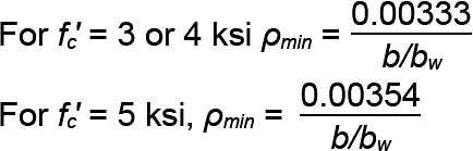
b / bw = 1.0 For fc' = 3 or 4 ksi, ρmin = 0.00333 For fc' = 5 ksi, ρmin = 0.00354 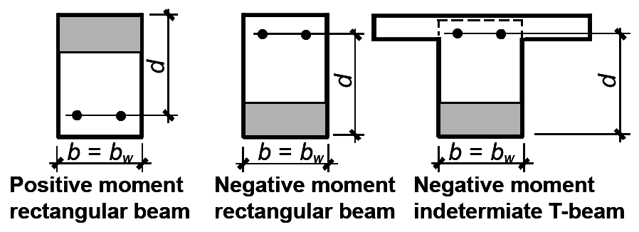 |
Minimum steel ratio for positive-moment T-beams:
 The effective width, b, of a positive-moment T-beam is smaller of the following: b = web width + ¼ clear beam span b = centerline distance between beams b = web width + 16 times slab thickness 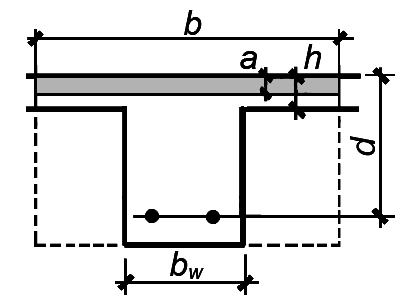 |
Minimum steel ratio for negative-moment determinate T-beams (e.g., precast sections and cantilevers):
For b / bw ≥ 2, ρmin = 0.00667(bw / b) for fc' = 3 or 4 ksi; and ρmin = 0.00708(bw / b) for fc' = 5 ksi. For b / bw < 2, ρmin = 0.00333 for fc' = 3 or 4 ksi; and ρmin = 0.00354(b / bw) for fc' = 5 ksi. 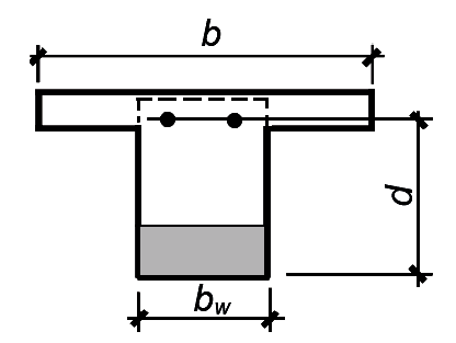 |
Minimum steel ratio for 1-way slabs:
ρmin = 0.00180(h/d) for slabs; the same steel ratio applies to shrinkage and temperature control steel perpendicular to slab longitudinal bar. 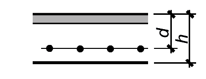 |
| Maximum steel ratio: ρmax = 0.01350 for fc' = 3 ksi ρmax = 0.01810 for fc' = 4 ksi ρmax = 0.02130 for fc' = 5 ksi |
Notes:
1. Mu ≤ φbd2R, where φ = 0.9, R = ρfy (1 – 0.5882ρfy / fc'), and ρ = As / bd. When using this table, R, fy, and fc' are in ksi units; b is the effective flange width (or effective width); bw is the beam stem or web width; and d is the effective depth, all in inch units. For positive-moment T-beams, results are valid only when the compressive stress block depth, a = ρfy d/(0.85fc') ≤ slab thickness, h. Steel strain at failure, εt = 0.005 for ρmax (that is, only tension-controlled sections are considered).
2. The values for ρmin tabulated for slabs assume that the slab effective depth, d, is equal to the slab thickness, h – 1 (inch units).
Table A-5.10: Development length in inches, ld, for 60 ksi deformed bars in tension, uncoated, normalweight concrete, with adequate spacing and/or stirrups and at least 12 in. of fresh concrete below the tension bars1,2,3,4,5
| fc' (psi) | Bar number ["in-lb" designation, with nominal diameter (in.) = bar number/8] | ||||||||||
|---|---|---|---|---|---|---|---|---|---|---|---|
| 3 | 4 | 5 | 6 | 7 | 8 | 9 | 10 | 11 | 14 | 18 | |
| 3000 | 27 | 36 | 45 | 53 | 62 | 71 | 80 | 90 | 100 | 121 | 161 |
| 4000 | 23 | 31 | 39 | 46 | 54 | 62 | 70 | 78 | 87 | 104 | 139 |
| 5000 | 21 | 28 | 34 | 41 | 48 | 55 | 62 | 70 | 78 | 93 | 124 |
Notes:
1. Bars must have a clear space between them at least equal to twice the bar diameter, that is, at least equal to 2db, and a clear cover at least equal to the bar diameter, db. Alternatively, if adequate stirrups or ties are used throughout the development length region to confine the bars and prevent splitting of the concrete, the minimum clear spacing requirement may be reduced to db. For bars not meeting these conditions, multiply values by 1.5.
2. Values assume "top" bars in tension with at least 12 in. of freshly-placed concrete below them; for "bottom" bars in tension (that is, bars placed for positive moment in beams), divide values by 1.3.
3. The development length may be reduced if the steel bar area provided is greater than the bar area required by multiplying the tabular value by the ratio of bar area required to bar area provided.
4. All of the modifications mentioned in Notes 1 and 2 are cumulative; that is, a value may be multiplied by one or more of the applicable modification factors.
5. In any case, the development length, ld, cannot be less than 12 in.
Table A-5.11: Development length for 60 ksi standard hooks in inches, ldh, for uncoated bars, normalweight concrete1,2,3,4,5,6,7,8
| fc' (psi) | Bar number ["in-lb" designation, with nominal diameter (in.) = bar number/8] | ||||||||||
|---|---|---|---|---|---|---|---|---|---|---|---|
| 3 | 4 | 5 | 6 | 7 | 8 | 9 | 10 | 11 | 14 | 18 | |
| 3000 | 7 | 11 | 16 | 21 | 26 | 32 | 38 | 46 | 53 | 70 | 108 |
| 4000 | 7 | 11 | 15 | 19 | 24 | 30 | 36 | 43 | 50 | 66 | 101 |
| 5000 | 7 | 10 | 14 | 19 | 24 | 29 | 35 | 41 | 48 | 63 | 98 |
Notes:
1. Development lengths must be multiplied by 1.333 where lightweight concrete is used.
2. Development lengths must be multiplied by 1.20 where epoxy-coated or zinc and epoxy dual-coated reinforcement is used.
3. Unlike the case for deformed bars in tension (Appendix Table A-5.10), the development length may not be reduced if the steel bar area provided is greater than the bar area required.
4. For hooked bars no greater in size than No. 11, the development length may be divided by 1.6 if the centerline spacing between hooked bars is at least 6db or if the total area of ties or stirrups confining the hooked bars is not less than 0.4 times the total area of the hooked bars.
5. For hooked bars no greater in size than No. 11, the development length can be divided by 1.25 if the cover on the side of the hooked bars (i.e., perpendicular to their longitudinal direction) is at least equal to 6db or if the hooked bars are inside a column core with side cover at least equal to 2.5 in.
6. All of the modifications mentioned in Notes 1 and 2 are cumulative; that is, a value may be multiplied by one or more of the applicable modification factors.
7. A 90° hook must be extended a distance of 12db below the bent portion of the bar, which in turn is defined by an inner radius that cannot be less than 3db for bars smaller than No. 9; 4db for No. 9, No. 10, and No. 11 bars; and 5db for No. 14 and No. 18 bars.
8. In any case, the development length for hooks, ldh, cannot be less than 8db or 6 in.
Table A-5.12: Development length in inches, ldc, for 60 ksi deformed bars in compression1,2,3,4
| fc' (psi) | Bar number ["in-lb" designation, with nominal diameter (in.) = bar number/8] | ||||||||||
|---|---|---|---|---|---|---|---|---|---|---|---|
| 3 | 4 | 5 | 6 | 7 | 8 | 9 | 10 | 11 | 14 | 18 | |
| 3000 | 9 | 11 | 14 | 17 | 20 | 22 | 25 | 28 | 31 | 38 | 50 |
| 4000 | 8 | 10 | 12 | 15 | 17 | 19 | 22 | 25 | 27 | 33 | 43 |
| 5000 | 8 | 9 | 12 | 14 | 16 | 18 | 21 | 23 | 26 | 31 | 41 |
Notes:
1. Values may be multiplied by 0.75 where adequately confined by a spiral or ties (specifically, with a minimum ¼ in. spiral at no more than a 4 in. pitch; or with No. 4 ties spaced at no more than 4 in. on center).
2. Values may be multiplied by the ratio of required steel bar area to provided steel bar area, except in cases where the anchorage is required to reach the yield stress, fy, or in certain high-risk seismic zones.
3. All of the modifications mentioned in Notes 1and 2 are cumulative; that is, a value may be multiplied by one or both of the applicable modification factors.
4. In any case, the development length for compression, ldc, cannot be less than 8 in.
Table A-5.13: Recommended minimum thickness (in.) of reinforced concrete beams and slabs for deflection control1,2
 |  | 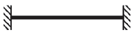 |  | |
| Beams | L / 16 | L / 18.5 | L / 21 | L / 8 |
| Slabs | L / 20 | L / 24 | L / 28 | L / 10 |
Notes:
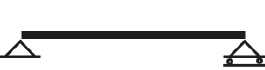
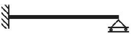
1. Beam diagram symbols in top row of tables represent the following conditions (from left to right): simply-supported; one end pinned and one end continuous; both ends continuous; and cantilever.
2. L = span (in.)
© 2020 Jonathan Ochshorn; all rights reserved. This section first posted November 15, 2020; last updated November 15, 2020.