
Contents | 1. Introduction to structural design | 2. Loads |
Introduction to wood | Material properties | Sectional properties | Design approaches | Construction systems | Tension elements |
The reduction in allowable compressive stress, Fc , to account for buckling is accomplished by multiplying Fc* by the column stability factor, CP. The value, Fc*, is the tabular value of compressive stress found in Appendix Table A-3.3, Fc, modified by all of the adjustment factors found in Appendix Table A-3.4 except CP. If all columns behaved according to the idealized model analyzed by Euler, the stability factor would be unnecessary, and σcr modified by some factor of safety would simply replace Fc as the allowable stress. That is, we would have:
In practice, given the pattern of column failure represented in Figure 1.56, the Euler equation must
be modified to account for crushing and non-elastic behavior, especially at low slenderness ratios.
The column stability factor, CP, does just that and more, replacing σcr with FcE (basically Euler's formula with a safety factor); adding a coefficient, c, to account for the non-ideal condition of various wood materials; and using statistical curve-fitting methods to match the empirical data. The slenderness ratio is simplified for a rectangular section, as only one cross-sectional dimension remains when values of Imin = HB3/12 (see Equation 1.9) and A = BH are inserted into the equation for radius of gyration (see Equation 1.13): r = ![]() =
=  =
= ![]() = 0.289B. Replacing the generic width term, B, with the wood industry's d, one can still see the Euler buckling equation struggling to assert itself within FcE = 0.822E'min/(le/d)2, which appears in both of the terms A and B within this opaque formulation for the column stability factor:
= 0.289B. Replacing the generic width term, B, with the wood industry's d, one can still see the Euler buckling equation struggling to assert itself within FcE = 0.822E'min/(le/d)2, which appears in both of the terms A and B within this opaque formulation for the column stability factor:

In Equation 3.10, A = [1 + (FcE / Fc*)]/(2c) and B = (FcE / Fc*)/c.
A full description of CP can be found in Appendix Table A-3.4, along with other adjustments to the allowable compressive stress.
For non-pin-ended columns, the unbraced length, le, is multiplied by an effective length coefficient (Appendix Table A-1.2) to account for the change in critical buckling stress resulting from more or less restraint at the column ends.
Problem definition. Check the capacity (allowable load) of a 10 × 10 Douglas Fir-Larch Select Structural column 8.5 ft high, used indoors, supporting live load (L), roof live load (i.e., construction live load, Lr), dead load (D) and snow load (S) as follows:
L = 40 kips; Lr = 20 kips; D = 50 kips; and S = 20 kips.
Solution overview. Find relevant material properties and adjustment factors; compute adjusted allowable stress; find capacity by multiplying cross-sectional area by adjusted allowable stress; compare capacity to governing load combination.
Problem solution
1. From Tables A-3.3 and A-3.9, find material properties Fc and Emin; the tabular (unadjusted) values are: Fc = 1150 psi, and Emin = 580,000 psi. These values are taken from "posts and timbers" since the cross section being analyzed is larger than 5 × 5 and the larger of the two cross-sectional dimensions is less than 4 in. greater than the smaller dimension.
2. Find adjustment factors for Fc:
a. From Appendix Table A-3.4 Part B, CM = 1.0.
b. From Appendix Table A-3.4 Part A, CF = 1.0.
c. Find load duration factor, CD, and the governing load combination: Two load combinations from Appendix Table A-2.7 (for allowable stress design) should be considered: D + L; and also D + 0.75L + 0.75(Lr or S). Wind and earthquake forces are not included, as they do not appear in the problem definition. The other listed load combinations in Appendix Table A-2.7 need not be considered, since it is evident that their effect will not be as severe. For the two selections, we divide each possible load combination by the load duration factor corresponding to the shortest load duration within that combination, as explained in Appendix Table A-3.10. The roof construction live load and snow load are not considered to act simultaneously. Starting with D + L, we get:
(D + L)/CD = (50 + 40)/1.0 = 90.0.
Then, looking at D + 0.75L + 0.75(Lr or S), we get either:
D + 0.75L + 0.75(S)/CD = (50 + 30 + 15)/1.15 = 82.61
or
D + 0.75L + 0.75(Lr)/CD = (50 + 30 + 15)/1.25 = 76.0
Dead plus live load (D + LD) governs, so CD = 1.00, and the load used to design (or analyze) the column is (D + L) = (50 + 40) = 90 kips. The duration of load factor, used to determine the governing condition, does not appear in the governing load itself. Rather, it will be applied to the allowable stress. It was not necessary to include the load combination consisting only of dead plus roof construction live load (D + Lr) since not only is the sum of these loads less than the combination of dead plus live load, but the duration of load factor (CD = 1.25) effectively makes the wood stronger for this combination.
d. From Appendix Table A-3.4, find the column stability factor, CP (to account for buckling):
From Appendix Table A-3.9, find E'min = Emin × CM. Since CM = 1.0 for timbers (do not confuse this adjustment with the value for CM applied to the allowable compressive stress, Fc), we get:
Emin = 580,000 psi; E'min = 580,000 × 1.0 = 580,000 psi.
le = 8.5 ft = 102 in.
d = 9.5 in.
FcE = 0.822E'min / (le / d)2 = 0.822 (580,000)/(102/9.5)2 = 4135.7 psi.
Fc* = FcCDCMCF = 1150(1.00)(1.0)(1.0) = 1150 psi.
c = 0.8 for sawn lumber.
A = [1 + (FcE /Fc*)]/(2c) = [1 + (3920.9/1150)]/1.6 = 2.87.
B = (FcE /Fc*)/c = (3920.9/1150)/0.8 = 4.50.
CP = A – ![]() = 2.87 –
= 2.87 –  = 0.934.
3. Compute adjusted allowable stress in compression: from step 2, Fc* = 1150 psi and CP = 0.934; so Fc' = Fc*(CP) = 1150(0.934) = 1075 psi.
4. Find capacity, P = Fc' × A: From Appendix Table A-3.12 the cross-sectional area for a 10 × 10, A = 90.25 in2; therefore, P = 1075(90.25) = 96,679 lb = 96.7 kips.
5. Check capacity: since the capacity of 96.7 kips ≥ governing load combination of 90 kips, the column is OK.
The value of CP = 0.934 indicates that buckling has reduced the column's allowable compressive stress to 93.4% of its "crushing" strength.
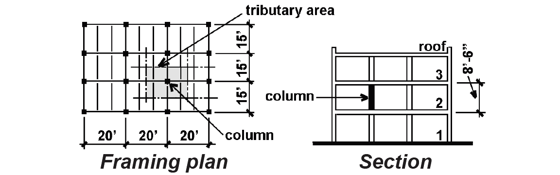
Problem definition. Find the lightest cross section for a wood column (Douglas Fir-Larch Select Structural) that is 8.5 ft high, used indoors, on the second floor of the 3-story building shown in Figure 3.17, supporting live load (L), roof live load (i.e., construction live load, Lr), dead load (D) and snow load (S) as follows:
L = 40 psf; Lr = 20 psf; D = 25 psf; and S = 30 psf.
Solution overview. Find relevant material properties and adjustment factors (assuming a provisional value for CP); compute adjusted allowable stress; find cross-sectional area by dividing load by adjusted allowable stress; select provisional cross section and analyze; repeat this step by selecting new cross section until capacity is just larger than load.
Problem solution
1. Using Appendix Tables A-3.3 and A-3.9, find material properties Fc and Emin; as in the last example, the tabular (unadjusted) value of Fc is 1150 psi, and the minimum modulus of elasticity, Emin = 580,000 psi. The value of Fc assumes a "post and timber" size.
2. Find adjustment factors for Fc, except for CP:
a. From Appendix Table A-3.4 Part B, CM = 1.0.
b. From Appendix Table A-3.4 Part A, CF = 1.0 (assuming that "dimension lumber" will not be used).
c. From Appendix Tables A-3.10 and A-2.7, CD depends on which load combination proves to
be critical. To find CD, divide each possible load combination by the load duration factor corresponding to the shortest load duration within each combination. The roof construction
live load and snow load are not considered to act simultaneously. The tributary area for the
typical column is 15 × 20 = 300 ft2 per floor for both the third floor live and dead load, and for the roof construction live load (or snow load) and dead load. Referring to Appendix Table A-2.2, part B, live load reduction for the third floor live load is appropriate since KLL times its tributary area of 300 ft2, or 1200 ft2, is greater than 400 ft2. For such an "influence area," the live load reduction coefficient is 0.25 + 15/ = 0.68, so the reduced live load is
0.68(40) = 27.2 psf. Roof construction/maintenance live loads are not reduced. The duration
of load factor, CD, is found by dividing the various load combinations by the appropriate load duration factors (where loads are computed by multiplying each square foot value by
the corresponding tributary area). Only two load combinations from Appendix Table A-2.7
need be considered, since the others evidently will not produce effects as severe. These
combinations are: D + L and also D + 0.75L + 0.75(Lr or S). In the latter combination, wind and earthquake forces are not included, as they do not appear in the problem definition. We divide each possible load combination by the load duration factor corresponding to the shortest load duration within that combination, as explained in Appendix Table A-3.10. The roof construction live load and snow load are not considered to act simultaneously. Starting with D + L, we get:
= 0.68, so the reduced live load is
0.68(40) = 27.2 psf. Roof construction/maintenance live loads are not reduced. The duration
of load factor, CD, is found by dividing the various load combinations by the appropriate load duration factors (where loads are computed by multiplying each square foot value by
the corresponding tributary area). Only two load combinations from Appendix Table A-2.7
need be considered, since the others evidently will not produce effects as severe. These
combinations are: D + L and also D + 0.75L + 0.75(Lr or S). In the latter combination, wind and earthquake forces are not included, as they do not appear in the problem definition. We divide each possible load combination by the load duration factor corresponding to the shortest load duration within that combination, as explained in Appendix Table A-3.10. The roof construction live load and snow load are not considered to act simultaneously. Starting with D + L, we get:
(D + L)/CD = [25(600) + 27.2(300)]/1.0 = 23,160 lb
Then, looking at D + 0.75L + 0.75(Lr or S), we get:
(D + .75L +.75S)/CD = [25(600) +.75(27.2)(300) +.75(30)(300)]/1.15 = 24,235 lb
or
(D + .75L +.75Lr)/CD = [25(600) +.75(27.2)(300) + .75(20)(300)]/1.25 = 20,496 lb.
The first case of the second load combination governs (using dead, live, and snow load), so CD = 1.15, and the load used to design the column is (D + .75L +.75S), or:
25(600) + 0.75(27.2)(300) + 0.75(30)(300) = 27,870 lb.
3. Select cross section by trial. The stability factor, CP, cannot be determined directly, since it depends upon the cross-sectional dimensions of the column which haven't yet been found. Design therefore turns into an iterative process, repeatedly making and testing assumptions about the column's stability until the tests (i.e., column analyses) confirm the assumptions. To begin the iterative process:
a. Assume a value for CP, for example, CP = 0.8.
b. Compute Fc* = Fc CD CM CF = 1150(1.15)(1.0)(1.0) = 1322.5 psi.
c. Compute Fc' = Fc* × CP = 1322.5(0.80) = 1058 psi.
d. Compute the provisional required cross-sectional area, Areq:
Areq = axial load / stress = 27,870/1058 = 26.3 in2.
Trial 1:
1. From Appendix Table A-3.12, select trial cross section based on provisional required area of 26.3 in2: A 6 × 6 has an area of 30.25 in2, but since the provisional required area of 26.3 in2 was based on an assumption about the column's stability (CP = 0.8), it is not immediately clear whether the choice is correct: what we must enter into at this point is the first step of an iterative process. We start by checking the 6 × 6 for its actual capacity and comparing this capacity to the applied load. This process is identical to the timber column analysis method illustrated in Example 3.3.
2. From Appendix Table A-3.4, find the actual column stability factor, CP, for the 6 × 6 column:
From Appendix Table A-3.9, find E'min = the adjusted minimum modulus of elasticity = Emin × CM; since CM = 1.0 for timbers, E'min = 580,000 psi.
le = 8.5 ft = 102 in.
d = 5.5 in.
FcE = 0.822E'min /(le / d)2 = 0.822(580,000)/(102/5.5)2 = 1386.2 psi.
Fc* = Fc CD CM CF = 1150(1.15)(1.0)(1.0) = 1322.5 psi (unchanged from above).
c = 0.8 for sawn lumber.
A = [1 + (FcE /Fc*)]/(2c) = [1 + (1386.2/1322.5)]/1.6 = 1.28.
B = (FcE /Fc*)/c = (1386.2/1322.5)/0.8 = 1.31.
CP = A – ![]() = 1.28 –
= 1.28 –  = 0.71.
3. Compute the adjusted allowable stress in compression:
Fc' = Fc* × CP = 1322.5(0.71) = 939.0 psi.
4. Find capacity, P = Fc' × A: From Appendix Table A-3.12, find cross-sectional area for 6 × 6: A = 30.25 in2; then, P = 939.0(30.25) = 28,405 lb.
5. Check capacity: the capacity of 28,405 lb is greater than the actual load of 27,870 lb. In other words, analysis shows that the 6 × 6 column is acceptable. If the capacity of a 6 × 6 column were insufficient, we would try the next largest size, i.e., a 6 × 8; and then an 8 × 8, etc. until a cross section was found with adequate capacity. In this case, however, even though the 6 × 6 is acceptable, it is possible that a smaller column size will also work, for two reasons: first, the next smaller size (a 4 × 6) falls under the dimension lumber size classification, which has a higher allowable compressive stress than what was assumed for posts and timbers. Second, allowable stresses for dimension lumber generally increase as the cross-sectional area gets smaller, due to the size factor adjustment. For these reasons, we now check a 4 × 6 column.
Trial 2:
1. From Appendix Table A-3.12, a 4 × 6 has an area of 19.25 in2.
2. From Appendix Table A-3.4, find the actual column stability factor, CP, for the 4 × 6 column:
From Appendix Table A-3.9, find E'min = the adjusted minimum modulus of elasticity = Emin × CM; since CM = 1.0 for any dry service condition, E'min = 690,000 psi.
le = 8.5 ft = 102 in.
d = 3.5 in.;
FcE = 0.822E'min /(le / d)2 = 0.822(690,000)/(102/3.5)2 = 667.8 psi;
Fc* = Fc CD CM CF = 1700(1.15)(1.0)(1.0) = 1955 psi (with the allowable stress, Fc, taken for dimension lumber).
c = 0.8 for sawn lumber.
A = [1 + (FcE /Fc*)]/(2c) = [1 + (667.8/1955)]/1.6 = 0.84.
B = (FcE /Fc*)/c = (667.8/1955)/0.8 = 0.43.
CP = A – ![]() = 0.84 –
= 0.84 –  = 0.32.
3. Compute the adjusted allowable stress in compression:
Fc' = Fc* × CP = 1955(0.32) = 615.9 psi.
4. Find capacity, P = Fc' × A: From Appendix Table A-3.12, find cross-sectional area for 4 × 6:
A = 19.25 in2; then, P = 615.9(19.25) = 11,856 lb.
5. Check capacity: the capacity of 11,856 lb is less than the actual load of 27,870 lb. Therefore, the 4 × 6 column is not OK: select the 6 × 6 column from Trial 1.
© 2020 Jonathan Ochshorn; all rights reserved. This section first posted November 15, 2020; last updated November 15, 2020.