
Contents | 1. Introduction to structural design | 2. Loads |
Introduction to wood | Material properties | Sectional properties | Design approaches | Construction systems | Tension elements | Columns |
Wood beams are generally designed for bending stress and then checked for shear and deflection. Using allowable stress design, the required section modulus is found by dividing the maximum bending moment by the adjusted allowable bending stress, Fb' , as shown in Equation 1.24. This adjusted value is found by multiplying the tabular value, Fb (Appendix Table A-3.5), by various adjustment factors. In addition to factors for load duration, wet service conditions, and size, three new adjustment factors are introduced for bending: a flat use factor, a repetitive member factor, and a beam stability factor (Appendix Table A-3.6).
The flat use factor, Cfu, accounts for the apparent increase in bending strength when beams are stressed about their weak axes. The repetitive member factor, Cr, accounts for the increased safety of joists and rafters made from dimension lumber when they are joined by floor or roof decks and spaced not more than 24 in. on center. Wood beams acting individually must be designed according to the most conservative assumptions regarding their actual strength; whereas closely-spaced joists or rafters enjoy an additional margin of safety — particularly heavy concentrated loads (or unusually weak joists or rafters) are "helped out" by the adjacent members. The beam stability factor, CL, accounts for the possibility of lateral-torsional buckling when the compression edge of a beam is not adequately braced. For beams continuously braced by roof or floor decks, as is often the case with dimension lumber, CL = 1.0. Otherwise, an effective length is found by multiplying the distance between lateral braces (often determined by the location of concentrated loads) by a coefficient and applying the formulas found in Appendix Table A-3.6.
For glued-laminated (glulam) beams only, the size factor is replaced by a "volume" factor, CV. Like the size factor, the volume factor is designed to account for the increased probability of brittle tensile failure in larger structural elements. Because the beam stability factor, CL, accounts for compressive buckling, while the volume factor accounts for tensile failure, it is not necessary to combine both of these factors when adjusting the allowable bending stress. Instead, only the smaller value of CV or CL is used for glulam beams.
Because some adjustment factors cannot be determined until the cross-sectional dimensions of the beam are known, the design process may become an iterative one, based on the analysis of trial sections. In this process, tabular values of allowable bending stress and modulus of elasticity are found in Appendix Tables A-3.5 and A-3.9; values for allowable shear stress, Fv, are found in Appendix Table A-3.7. Shear stress is only adjusted for duration of load and wet service conditions (Appendix Table A-3.8). When computing deflections, the only adjustment to modulus of elasticity, E, is for wet service conditions (Appendix Table A-3.9). The average modulus of elasticity (E), and not the minimum modulus of elasticity (Emin), is used in deflection calculations.
In the examples that follow, the maximum shear force, V, could have been reduced by considering the value at a distance, d, from the face of the supports, as illustrated in Figure 1.67. Where shear does not appear to be a critical factor in the design of the beam, this reduction is usually unnecessary; however, if shear appears to govern the beam design, it may be beneficial to use the reduced value of V in the calculation of actual shear stress.
Problem definition. Can a 2 × 8 Hem-Fir No. 2 joist, spaced 16 in. on center, be used in a residential application, spanning 12 ft? Assume a dead load corresponding to that listed in Appendix Table A-2.1 for wood floor systems with 2 × 10 joists.
Solution overview. Find loads; check bending stress (or required section modulus); check shear stress (or required cross-sectional area); check deflection.
Problem solution
1. Find loads:
a. From Appendix Table A-2.2, the live load, L = 40 psf; the live load distributed on 1 linear foot of the joist is L = 40(16/12) = 53.33 lb/ft. Live load reduction does not apply since ATKLL (the tributary area multiplied by the live load element factor — see Appendix Table A-2.2, part B — is less than 400 ft2.
b. From Appendix Table A-2.1, the dead load, D = 10.5 psf; the dead load distributed on 1 linear foot of the joist is D = 10.5(16/12) = 14 lb/ft.
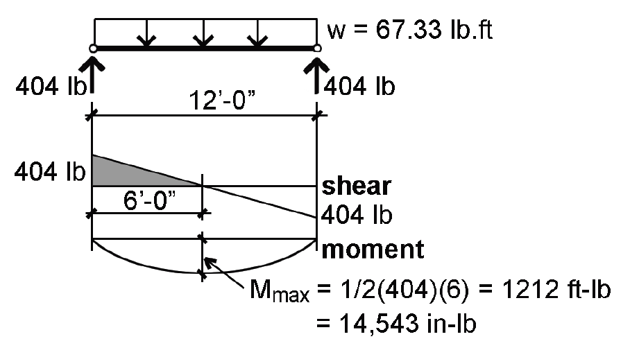
c. The total distributed load, w = 53.33 + 14.0 = 67.33 lb/ft.
2. Create load, shear and moment diagrams as shown in Figure 3.18 to determine critical (i.e., maximum) shear force and bending moment.
3. Find adjusted allowable bending stress:
a. From Appendix Table A-3.5, find the tabular allowable bending stress: Fb = 850 psi.
b. From Appendix Table A-3.6, find all relevant adjustments: CF = 1.2; Cr = 1.15; CM = CD = 1.0.
c. Multiply the tabular stress value by the adjustments to get the adjusted allowable stress: Fb' = 850(1.2)(1.15) = 1173 psi.
4. From Equation 1.24, compute the required section modulus: Sreq = M/Fb' = 14,543/1173 = 12.4 in3.
5. From Appendix Table A-3.12, check the actual section modulus for a 2 × 8, bent about its strong (x) axis: Sx = 13.14 in3; since actual Sx = 13.14 in3 ≥ required Sx = 12.4 in3, the 2 × 8 section is OK for bending.
6. Find adjusted allowable shear stress:
a. From Appendix Table A-3.7, the tabular allowable shear stress, Fv = 150 psi.
b. From Appendix Table A-3.8, find all relevant adjustments: CM = 1.0; CD = 1.0.
c. Multiply the tabular stress value by the adjustments to get the adjusted allowable stress: Fv' = 150(1.0)(1.0) = 150 psi.
7. From Equation 1.29, compute the required area, Areq = 1.5V/Fv' = 1.5(404)/150 = 4.04 in2.
8. From Appendix Table A-3.12, check the actual area of the cross section: Aact = 10.88 in2; since Aact = 10.88 in2 ≥ Areq = 4.04 in2, the 2 × 8 section is OK for shear.
9. From Appendix Table A-1.3, find the allowable total-load deflection for a floor joist: ΔTallow = span/240 = (12 × 12)/240 = 0.6 in.; and the allowable live-load deflection for a floor joist: ΔLallow = span/360 = (12 × 12)/360 = 0.4 in.
10. Using Appendix Table A-3.15, check the actual total-load deflection. ΔTact = CP(L/12)3/(EI) where:
C = 22.46.
L = 12 × 12 = 144 in. (We are using the same symbol, L, for span and "live load"; the meaning should be clear from the context).
P = w(L/12) = 67.33(144/12) = 808 lb.
E = 1,300,000 psi (Appendix Table A-3.9).
Ix = 47.63 in4 (Appendix Table A-3.12).
ΔTact = 22.46(808)(144/12)3/(1,300,000 × 47.63) = 0.5 in.
Since ΔTact = 0.5 in. ≤ ΔTallow = 0.6 in., the beam is OK for total-load deflection.
11. Using Appendix Table A-3.15, check the actual live-load deflection. ΔLact = CP(L/12)3/(EI) where:
C = 22.46.
L = 12 × 12 = 144 in. (We are using the same symbol, L, for span and "live load"; the meaning should be clear from context).
P = w(L/12) = 53.33(144/12) = 640 lb (Use live load only!).
E = 1,300,000 psi (Appendix Table A-3.9).
Ix = 47.63 in4 (Appendix Table A-3.12).
ΔLact = 22.46(640)(144/12)3/(1,300,000 × 47.63) = 0.4 in.
Since ΔLact = 0.4 in. ≤ ΔLallow = 0.4 in., the beam is OK for live-load deflection.
12. Conclusion: The 2 × 8 is OK for bending, shear and deflection. Therefore it is acceptable.
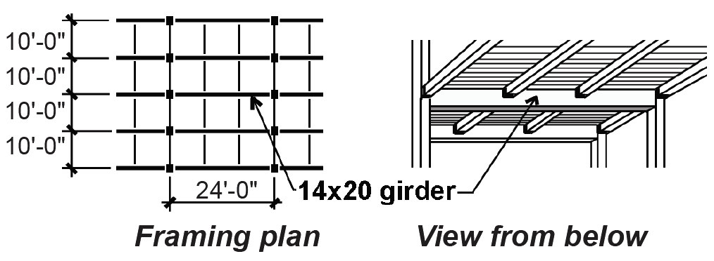
Problem definition. Can a 14 × 20 Hem-Fir No. 2 girder be used in a "heavy timber" office building application, as shown in Figure 3.19? Assume that only the beams framing into the girder provide lateral bracing at the third points. Assume a total dead load of 18 psf and a live load corresponding to office occupancy.
Solution overview. Find loads; check bending stress (or required section modulus); check shear stress (or required cross-sectional area); check deflection.
Problem solution
1. Find loads:
a. From Appendix Table A-2.2, the live load for office occupancy, L = 50 psf; with live load reduction, we get: L = 50(0.25 + 15/ ) = 50(0.935) = 46.7 psf.
b. The dead load, D = 18 psf (given).
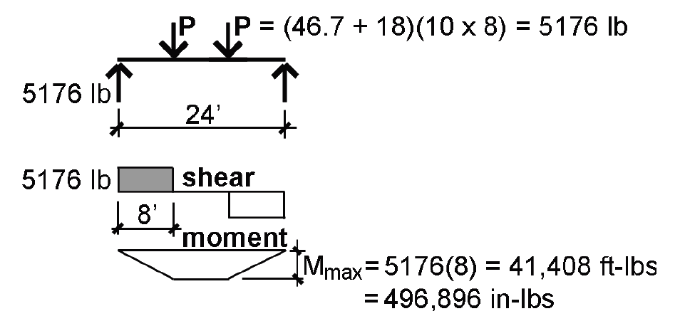
c. A total concentrated load, PL, acts on a tributary area of 10 × 8 = 80 ft2, so P = (D + L)(80) = (18 + 46.7)(80) = 5176 lb.
2. Create load, shear and moment diagrams as shown in Figure 3.20 to determine critical (i.e., maximum) shear force and bending moment.
3. From Appendix Table A-3.5, the tabular value is Fb = 675 psi.
4. Find the adjustments to the allowable bending stress:
a. From Appendix Table A-3.6: CF = (12/19.5)1/9 = 0.95.
b. From Appendix Table A-3.6: Cr = 1.0.
c. From Appendix Table A-3.6: CM = 1.0.
d. From Appendix Table A-3.6: CD = 1.0.
e. In addition, the beam stability factor must be computed:
CL = A – ![]() where:
where:
le = 1.68lu = (1.68)(8 × 12) = 161 in. (for concentrated loads providing lateral support at the third points)
E'min = 400,000 psi (from Appendix Table A-3.9)
b = 13.5 in.; d = 19.5 in. ("green" dimensions of a 14 × 20 from Appendix Table A-3.12)
Fb* = FbCMCDCF = 675(1.0)(1.0)(0.95) = 640 psi
FbE = 1.20(13.52)(400,000)/(161 × 19.5) = 27,864
A = (1 + 27,864/640)/1.9 = 23.44
B = (27,864/640)/0.95 = 45.83
f. CL = A – ![]() = 23.44 –
= 23.44 –  = 0.999.
5. The adjusted allowable stress, Fb' = Fb*CL = 640(0.999) = 639 psi.
6. From Equation 1.24, compute the required section modulus: Sreq = M/Fb' = 496,896/639 = 778 in3.
7. From Appendix Table A-3.12, check the actual section modulus about the strong (x) axis: Sx = 855.6 in3; since the actual Sx = 855.6 in3 ≥ the required Sx = 778 in3, the section is OK for bending.
8. Find the adjusted allowable shear stress:
a. From Appendix Table A-3.7, the tabular allowable shear stress, Fv = 140 psi.
b. From Appendix Table A-3.8, find all relevant adjustments: CM = 1.0; CD = 1.0.
c. The adjusted allowable shear stress, Fv' = 140(1.0)(1.0) = 140 psi.
9. From Equation 1.29, compute the required area, Areq = 1.5V/Fv' = 1.5(5176)/140 = 55.5 in2.
10. From Appendix Table A-3.12, check the actual area of a 14 × 20 cross section: Aact = 263.3 in2. Since Aact = 263.3 in2 ≥ Areq = 55.5 in2, the section is OK for shear.
11. From Appendix Table A-1.3, find the allowable total-load deflection for a floor beam: ΔTallow = span/240 = (24 × 12)/240 = 1.2 in.; and the allowable live-load deflection for a floor joist: ΔTallow = span/360 = (24 × 12)/360 = 0.8 in.
12. From Appendix Table A-1.3, check the actual total-load deflection: ΔTact = CP(L/12)3/(EI) where:
C = 61.34.
L = 24 × 12 = 288 in.
P = (46.7 + 18)(10 × 8) = 5176 lb.
E = 1,100,000 psi (from Appendix Table A-3.9).
I = 8342 in4 (from Appendix Table A-3.12).
ΔTact = 61.34(5176)(288/12)3/(1,100,000 × 8342) = 0.48 in. Since ΔTact = 0.48 in. ≤ ΔTallow = 1.2 in., the girder is OK for total-load deflection.
13. From Appendix Table A-3.15, check the actual live-load deflection: ΔLact = CP(L/12)3/(EI) where:
C = 61.34.
L = 24 × 12 = 288 in.
P = 46.7(10 × 8) = 3736 lb (Use live load only!)
E = 1,100,000 psi (from Appendix Table A-3.9).
I = 8342 in4 (from Appendix Table A-3.12).
ΔLact = 61.34(3736)(288/12)3/(1,100,000 × 8342) = 0.35 in. Since ΔLact = 0.35 in. ≤ ΔLallow = 0.8 in., the girder is OK for live-load deflection.
14. Conclusion: The 14 × 20 is OK for bending, shear and deflection. Therefore it is acceptable.
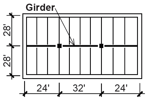
Problem definition. Design a 32 ft-long glulam roof girder of stress class 20F-1.5E for the one-story industrial building shown in the framing plan (Figure 3.21). Assume a snow load, S = 30 psf and a dead load, D = 20 psf. Use a beam width of 8-3/4 in., with 1-1/2 in. laminations (i.e., assume that "Western Species" will be used). Beams framing into the girder provide lateral bracing only at the quarter points. Use snow load only in computing "live load" deflection, and assume that the deflection criteria will be based on a roof structure with no ceiling.
Solution overview. Find loads; begin iterative design process by assuming unknown adjustments to allowable stresses; then check bending stress (required section modulus), shear stress (required cross-sectional area) and deflection, as in analysis examples. Recompute if necessary with bigger (or smaller) cross section until bending, shear and deflection are OK.
Problem solution
1. Find loads:
S = 30 psf (given).
D = 20 psf (given).
From Appendix Table A-2.7, it can be seen by examining the various load combinations that the most severe effects occur with the combination: dead load plus snow load, or D + S.
Using D + S, the total concentrated load, P, acts on tributary area of 28 × 8 = 224 ft2, so: P = (D + S) × (tributary area) = (20 + 30)(224) = 11,200 lb.
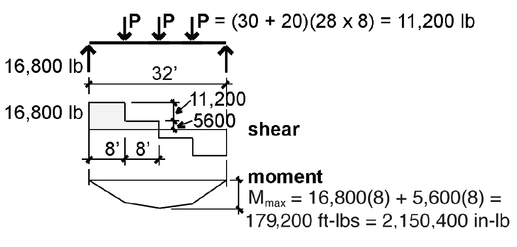
2. Create load, shear and moment diagrams as shown in Figure 3.22 to determine critical (i.e., maximum) shear force and bending moment.
3. Find provisional adjusted allowable bending stress:
a. From Appendix Table A-3.5 part D, the design (tabular) value for bending is: Fb = 2000 psi.
b. From Appendix Table A-3.6, the relevant adjustments are as follows: Cr = 1.0; CM = 1.0; CD = 1.15; CL and CV cannot yet be determined, since they depend on the actual cross section size; for now, choose any reasonable value for the smaller of CL or CV; for example, assume that the smaller of CL or CV = 0.9.
c. The adjusted value for allowable bending stress, Fb' = 2000(1.15)(0.9) = 2070 psi.
4. From Equation 1.24, compute the required section modulus: Sreq = M/Fb' = 2,150,400/2070 = 1039 in3.
5. Compute the required depth, d, based on the section modulus for a rectangular cross section, S = bd2/6 = 1039 in3 and b = 8.75 in. (given). In this case, 8.75d2/6 = 1039, from which d = 26.7 in. Rounding up to the first multiple of 1.5 in. (the depth of an individual lamination), we get: d = 27 in.
Trial 1: 8-3/4 in. × 27 in. cross section
1. Find allowable bending stress: as before, Fb = 2000 psi.
2. Find adjustments to allowable bending stress (Appendix Table A-3.6):
Cr = 1.0.
CM = 1.0.
CD = 1.15.
CL or CV (the smaller value still needs to be determined).
CV = (21/32)1/10(12/27)1/10(5.125/8.75)1/10 = 0.84.
CL = A – ![]() where:
where:
le = 1.54 lu = (1.54)(8 × 12) = 148 in.
E'min = 780,000 psi, from Appendix Table A-3.9 parts B and C.
b = 8.75 in.; d = 27 in.
Fb* = FbCD = 2000(1.15) = 2300 psi.
FbE = 1.20(8.752)(780,000)/(148 × 27) = 17,934.
A = (1 + 17,934/2300)/1.9 = 4.63.
B = (17,934/2300)/0.95 = 8.21.
CL = A – ![]() = 4.63 –
= 4.63 –  = 0.99.
Since CV = 0.84 < CL = 0.99, use CV only.
3. The adjusted design value for bending is Fb' = Fb*CV = 2300(0.84) = 1932 psi.
4. From Equation 1.24, compute the required section modulus: Sreq = M/Fb' = 2,150,400/1932 = 1113 in3.
5. Check that actual section modulus is greater or equal to required section modulus: actual Sx = bd2/6 = 8.75(272)/6 = 1063 in3; since actual Sx = 1063 in3 < required Sx = 1113 in3, the section is not OK for bending. Try next larger section (increase depth, not width!).
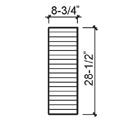
Trial 2: 8-3/4 in. × 28-1/2 in. cross section (Figure 3.23)
1. Find allowable bending stress: as before, Fb = 2000 psi.
2. Find adjustments to allowable bending stress (Appendix Table A-3.6):
Cr = 1.0.
CM = 1.0.
CD = 1.15.
CL or CV (the smaller value still needs to be determined).
CV = (21/32)1/10(12/28.5)1/10(5.125/8.75)1/10 = 0.83.
CL = A – ![]() where:
where:
le = 1.54 lu = (1.54)(8 × 12) = 148 in.
E'min = 780,000 psi, from Appendix Table A-3.9 parts B and C.
b = 8.75 in.; d = 28.5 in.
Fb* = FbCD = 2000(1.15) = 2300 psi.
FbE = 1.20(8.752)(780,000)/(148 × 28.5) = 16,990.
A = (1 + 16,990/2300)/1.9 = 4.41.
B = (16,990/2300)/0.95 = 7.78.
CL = A – ![]() = 4.41 –
= 4.41 –  = 0.99.
Since CV = 0.83 < CL = 0.99, use CV only.
3. The adjusted design value for bending is Fb' = Fb*CV = 2300(0.83) = 1909 psi.
4. From Equation 1.24, compute the required section modulus: Sreq = M/Fb' = 2,150,400/1909 = 1126 in3.
5. Check that actual section modulus is greater or equal to required section modulus: actual Sx = bd2/6 = 8.75(28.52)/6 = 1185 in3; since actual Sx = 1185 in3 ≥ required Sx = 1126 in3, the section is OK for bending.
6. Find adjusted allowable shear stress:
a. From Appendix Table A-3.7 part C, the design value for shear, Fv = 195 psi.
b. From Appendix Table A-3.8, the relevant adjustments are as follows: CM = 1.0; CD = 1.15.
c. The adjusted allowable stress for shear, Fv' = 195(1.15) = 224.25 psi.
7. Based on Equation 1.29, the required cross-sectional area to resist shear, Areq = 1.5V/Fv' = 1.5(16,800)/224.25 = 112.4 in2.
8. Check actual cross-sectional area = 8.75 × 28.5 = 249.4 in2; since the actual area, Aact = 249.4 in2 ≥ Areq = 112.4 in2, section is OK for shear.
9. From Appendix Table A-1.3, the allowable total load deflection for a roof with no ceiling, ΔTallow = span/120 = 32(12)/120 = 3.20 in.; and the allowable live load (actually snow load in this case) deflection for a roof with no ceiling, ΔLallow = span/180 = 32(12)/180 = 2.13 in.
10. From Appendix Table A-3.15, the actual total load deflection is ΔTact = CP(L/12)3/(EI) where:
C = 85.54.
P = (S + D)(tributary area) = (30 + 20)(28 × 8) = 11,200 lb.
L = 32 × 12 = 384 in.
E' = 1,500,000 psi, from Appendix Table A-3.9 parts A and C. The "average" adjusted modulus of elasticity, E', is used for deflection calculations, whereas the adjusted minimum modulus of elasticity, E'min, is used in buckling or stability calculations.
I = bd3/12 = (8.75)(28.53)/12 = 16,879.6 in4 (Equation 1.8).
ΔTact = 85.54(11,200)(384/12)3/(1,500,000 × 16,880) = 1.24 in. Since ΔTact = 1.24 in. ≤ ΔTallow = 3.20 in., the beam is OK for total-load deflection.
11. From Appendix Table A-3.15, the actual live (snow) load deflection is Δact = CP(L/12)3/(EI) where:
C = 85.54.
P = (S)(tributary area) = (30)(28 × 8) = 6720 lb (Use snow load only!).
L = 32 × 12 = 384 in.
E' = 1,500,000 psi, from Appendix Table A-3.9 parts A and C. The "average" adjusted modulus of elasticity, E', is used for deflection calculations, whereas the adjusted minimum modulus of elasticity, E'min, is used in buckling or stability calculations.
I = bd3/12 = (8.75)(28.53)/12 = 16,879.6 in4.
ΔLact = 85.54(6720)(384/12)3/(1,500,000 × 16,880) = 0.74 in. Since ΔLact = 0.74 in. ≤ ΔLallow = 2.13 in., the beam is OK for live load (snow load) deflection.
12. Conclusion: The 8-3/4 in. × 28-1/2 in. section is OK for bending, shear and deflection. Therefore it is acceptable.
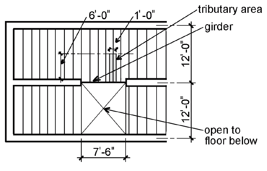
Problem definition. Design a Douglas Fir-Larch (North) No.1/No.2 girder using 4× lumber to support a residential live load as shown in Figure 3.24. Assume 10.5 psf for dead load. Loads on the girder can be modeled as being uniformly distributed since joists are spaced closely together.
Solution overview. Find loads; find known adjustments to allowable bending stress; use Appendix Table A-3.16 to directly compute lightest cross section for bending; check for shear and deflection. Alternatively, begin iterative design process by assuming unknown adjustments to allowable stresses; then check bending stress (required section modulus), shear stress (required cross-sectional area) and deflection, as in analysis examples. Recompute if necessary with bigger (or smaller) cross section until bending, shear and deflection are OK.
Problem solution
1. Find loads:
a. From Appendix Table A-2.2, the live load for a residential occupancy, L = 40 psf.
b. The dead load, D = 10.5 psf (given).
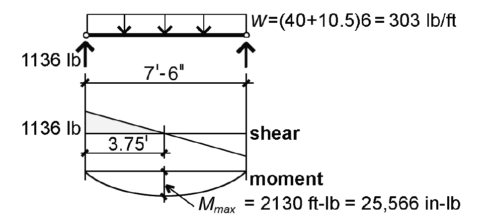
c. The total distributed load, w = (D + L)(tributary area) = (10.5 + 40)(6) = 303 lb/ft. Live load reduction does not apply since KLL times the tributary area is less than 400 ft2. The tributary area for w is measured along one linear foot of the girder, in the direction of its span, as shown in the framing plan (Figure 3.24).
2. Create load, shear and moment diagrams as shown in Figure 3.25 to determine critical (i.e., maximum) shear force and bending moment.
3. Find partially-adjusted allowable bending stress:
a. From Appendix Table A-3.5, the design (tabular) value for bending stress, Fb = 850 psi.
b. From Appendix Table A-3.6, the following adjustments can be determined: Cr = 1.0; CM = 1.0; CD = 1.0; CL = 1.0 (assume continuous bracing by floor deck). The size factor, CF, need not, and cannot, be determined at this point.
c. The adjusted value for bending stress, with all adjustments known except for CF, is Fb'' = 850CF psi (the double "prime" distinguishes this value from the fully adjusted value, Fb').
4. From Equation 1.24, compute the required section modulus: Sreq = M/Fb' = M/(850CF) = 25,566/(850CF). This can be rewritten as CFSreq = M/(850) = 25,566/(850) = 30.08 in3.
5. Rather than doing several "trial" designs, it is possible to find the correct cross section for bending directly, by using a table of combined size factors (CF) and section moduli (Sx) with the lightest values highlighted. In this method, the adjusted allowable stress is computed without the size factor, since CF is combined with the section modulus in the table. Appendix Table A-3.16 indicates directly that the lightest 4× section for bending is a 4 × 8, based on a combined CFSx value of 39.86 in3, which is larger than the required value of CFSreq = 30.08 in3 found in step 4. Appendix Table A-3.16 also shows that a 2 × 12 is actually the lightest acceptable section for bending, since it is the first bold-faced (highlighted) entry with a value of CFSx greater than or equal to 30.08 in3. However, in this problem, a 4× section was called for, so we provisionally select the 4 × 8 section.
6. Find adjusted allowable shear stress:
a. From Appendix Table A-3.7, the design (tabular) allowable shear stress Fv = 180 psi.
b. From Appendix Table A-3.8, there are no adjustments for shear stress; i.e.: CM = 1.0; CD = 1.0.
c. The adjusted value for allowable shear stress, Fv' = 180 psi.
7. Based on Equation 1.29, the required cross-sectional area to resist shear, Areq = 1.5V/Fv' = 1.5(1136)/180 = 9.47 in2.
8. From Appendix Table A-3.12, we can check the actual area of the cross section, Aact = 25.38 in2; since Aact = 25.38 in2 ≥ Areq = 9.47 in2, the section is OK for shear.
9. From Appendix Table A-1.3, find the allowable total-load deflection for a floor beam: ΔTallow = span/240 = (7.5 × 12)/240 = 0.375 in.; and the allowable live-load deflection for a floor joist: Δallow = span/360 = (7.5 × 12)/360 = 0.25 in.
10. From Appendix Table A-3.15, we can check the actual total-load deflection: ΔTact = CP(L/12)3/(EI) where:
C = 22.46.
L = 7.5 × 12 = 90 in.
P = w(L/12) = (40 + 10.5)(6)(90/12) = 2272.5 lb.
E = E' = 1,600,000 psi (from Appendix Table A-3.9).
I = 111.1 in4 (directly from Appendix Table A-3.12, or from the equation, I = bd3/12).
ΔTact = 22.46(2272.5)(90/12)3/(1,600,000 × 111.1) = 0.12 in. Since ΔTact = 0.12 in. ≤ ΔTallow = 0.375 in., the beam is OK for total-load deflection.
11. From Appendix Table A-3.15, we can check the actual live-load deflection: ΔLact = CP(L/12)3/(EI) where:
C = 22.46.
L = 7.5 × 12 = 90 in.
P = w(L/12) = (40 × 6)(90/12) = 1800 lb (Use live load only!).
E = E' = 1,600,000 psi (from Appendix Table A-3.9).
I = 111.1 in4 (directly from Appendix Table A-3.12, or from the equation, I = bd3/12).
ΔLact = 22.46(1800)(90/12)3/(1,600,000 × 111.1) = 0.096 in. Since ΔLact = 0.096 in. ≤ ΔLallow = 0.25 in., the beam is OK for deflection.
12. Conclusion: The 4 × 8 section is OK for bending, shear and deflection. Therefore it is acceptable.
It is also possible to find the lightest 4× section using an iterative design process without Appendix Table A-3.16. Using this method, the size factor, CF, would need to be assumed, and then checked after a provisional cross section is found, as follows:
1. Assuming a size factor, CF = 1.0, the adjusted allowable bending stress becomes Fb' = 850(1.0) = 850 psi. Then, from Equation 1.24, we compute the required section modulus: Sreq = M/Fb' = M/850 = 25,566/850 = 30.08 in3.
2. From Appendix Table A-3.12, we provisionally select a 4 ×10 with actual Sx = 32.38 in3.
Trial 1: 4 × 10 cross section
1. Find actual adjusted allowable bending stress: The design (tabular) value remains Fb = 850 psi; the actual size factor for a 4 × 10 is CF = 1.20, so the adjusted allowable bending stress, Fb' = 850(1.20) = 1020 psi. Since this value for a 4 ×10 is greater than the allowable stress initially assumed, the 4 ×10 must be OK for bending. But is it the lightest acceptable choice? Because the size factor actually increases for smaller sections, we must try the next smaller size.
Trial 2: 4 × 8 cross section
1. Find actual adjusted allowable bending stress for the 4 × 8: The size factor, CF = 1.3, so the adjusted allowable bending stress, Fb' = 850(1.3) = 1105 psi.
2. From Equation 1.24, compute the required section modulus: Sreq = M/Fb' = 25,566/1105 = 23.14 in3.
3. From Appendix Table A-3.12, the actual section modulus for a 4 × 8, Sx = 30.66 in3; since actual Sx = 30.66 in3 ≥ Sreq = 23.14 in3, the 4 × 8 section is OK for bending.
4. Shear and deflection for the 4 × 8 are checked as shown above, using the first method, and are both OK.
5. Conclusion: The 4 × 8 section is OK for bending, shear and deflection. Therefore it is acceptable. But what about a 4 × 6, with a size factor just as large?
Trial 3: 4 × 6 cross section
1. Find actual adjusted allowable bending stress for the 4 × 6: The size factor, CF = 1.3, so the adjusted allowable bending stress, Fb' = 850(1.3) = 1105 psi.
2. From Equation 1.24, compute the required section modulus: Sreq = M/Fb' = 25,566/1105 = 23.14 in3.
3. From Appendix Table A-3.12, the actual section modulus for a 4 × 6, Sx = 17.65 in3; since actual Sx = 17.65 in3 < Sreq = 23.14 in3, the 4 × 6 section is not OK for bending.
4. Conclusion: Since the 4 × 6 is not OK, select the 4 × 8 section.
© 2020 Jonathan Ochshorn; all rights reserved. This section first posted November 15, 2020; last updated November 15, 2020.