
Contents | 1. Introduction to structural design | 2. Loads |
Introduction to wood | Material properties | Sectional properties | Design approaches | Construction systems | Tension elements | Columns | Beams |
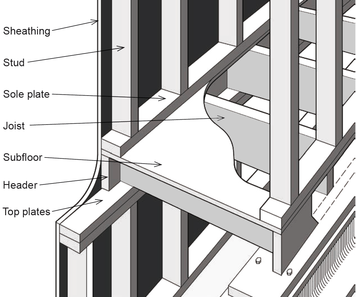
Were it only the force of gravity — the resistance to live and dead loads — that wood structures encountered, it would be possible to assemble structural elements by literally resting one upon the other: i.e., by stacking them so that the ends of beams or the bottom of posts bear upon plates, beams, or posts positioned below them, with the surfaces in contact between elements subject only to compressive stress. However, because there are always other loads, including both the horizontal and upward components of wind and earthquake forces, and various impact loads that could dislodge or overturn elements designed exclusively for downward-acting loads, the idealized condition represented by this model must be adjusted by using fasteners that respond to those non-gravity forces as well. That being said, the basic idea of stacking one wood element on top of the other remains an important strategy for assembling many wood structures, as can be seen by examining a typical light wood framing system (Figure 3.26): in such cases, the necessary resistance to lateral and upward loads, from foundation to roof, is often accomplished by superimposing metal straps and other fasteners at key joints.
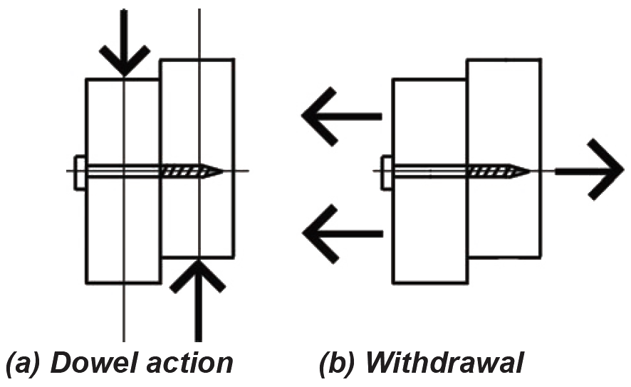
Aside from the use of metal straps, plates, and other more complex hangers and brackets, wood elements are typically connected using nails, bolts, and screws (of the screws, we will be considering only lag screws, sometimes referred to as "lag bolts," here). These fasteners can be used in two distinct ways: primarily as dowels inserted perpendicular to the direction of load; but also in withdrawal, i.e., subject to tension forces parallel to the direction of load. The designation for the capacity of a dowel-type fastener (i.e., a fastener stressed in shear) is Z; the capacity of a fastener used in withdrawal is designated as W, as shown in Figure 3.27. In both cases, the capacity must be multiplied by adjustment factors; the adjusted capacities are designated Z' and W' respectively.
Where the head of a lag screw or bolt, or the nut of a bolt, comes in contact with a wood member, a circular or square washer is inserted between the metal and wood surfaces in order to distribute the load imparted by the metal fastener over a greater surface area of wood. This is a requirement for bolts and lag screws subjected to either shear or tension.
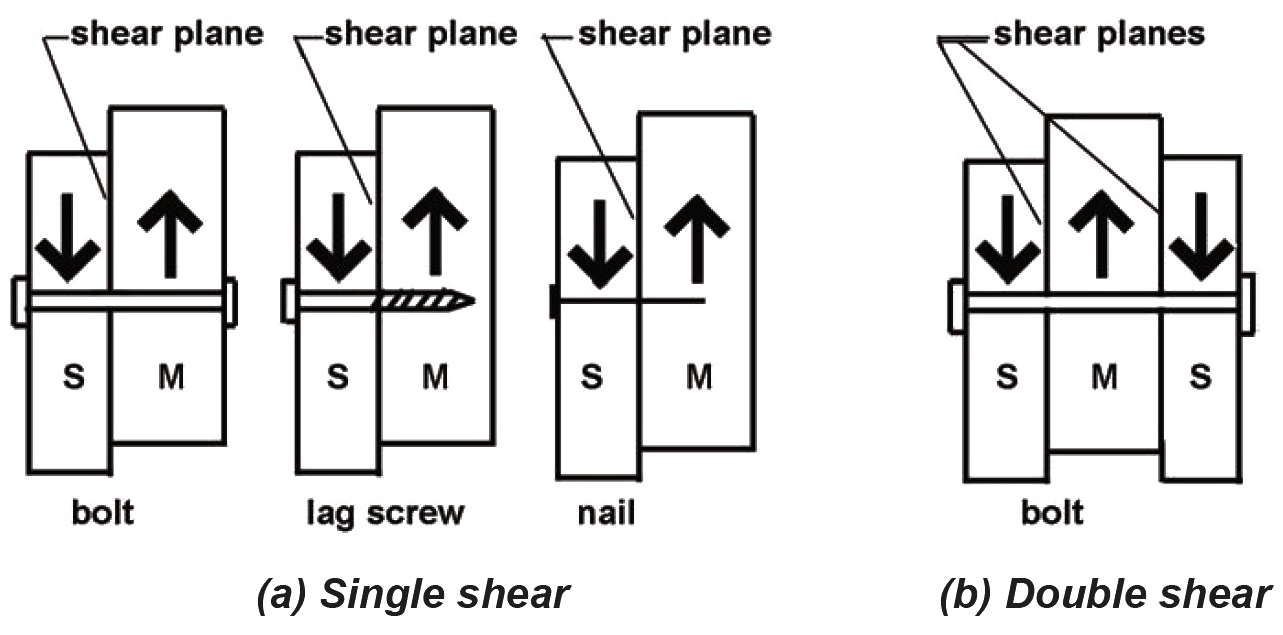
With respect to dowel-type action, nails and screws typically connect only two members (the side member being the piece into which the nail is first hammered or the screw is first inserted; the main member being the piece connected behind the side member). Such connections are in "single shear," since there is only a single shear plane between the side and main member (Figure 3.28a). Bolts can connect two members in single shear, but also can connect three members in "double shear." In the latter case, the "main member" is in the center, with the two outside members defined as "side members," as shown in Figure 3.28b. Where bolts are used in single shear, the main member is defined as the thicker piece (if any), since either side could serve as the point of insertion without altering the behavior of the connection.
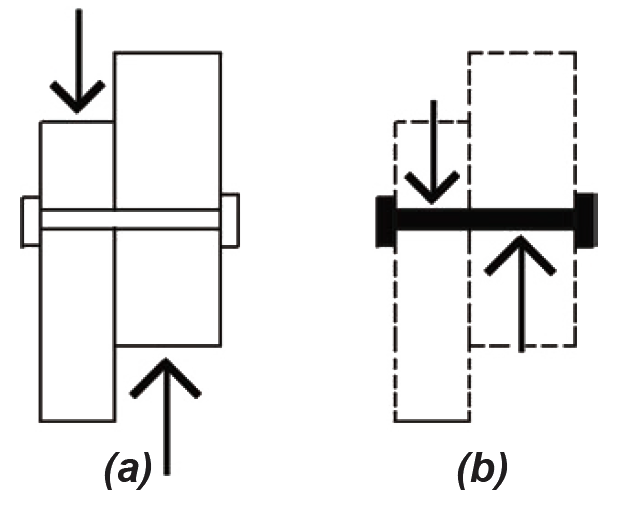
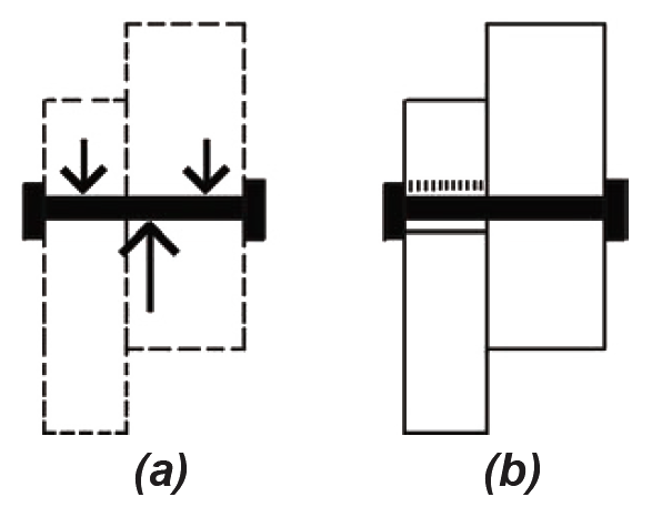
Typical idealized diagrams representing the forces on dowel-type fasteners in single shear are often misleading, since neither the structure (Figure 3.29a) nor the fasteners themselves (Figure 3.29b) would be in rotational equilibrium with only a single force couple.
The actual pattern of forces acting on such fasteners is more complex, since these forces must satisfy all three equations of equilibrium. Several possibilities exist for the arrangement of forces on the fasteners that are consistent with the requirements for equilibrium. For example, as shown in Figure 3.30a, the force acting downward on the left-hand member can be "balanced" by two forces in the right-hand member; critical stress patterns applied to the wood by the fasteners are shown schematically in Figure 3.30b, assuming that only stresses in the lefthand member have reached critical values. This pattern of stress is designated Mode I.
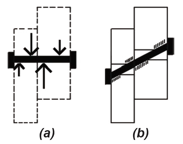
Several other patterns of force and stress can develop in the wood connection. Figure 3.31 illustrates Mode II, in which critical stresses develop in both members. The inclination of the fastener (Figure 3.31b) is exaggerated to show how the pattern of critical stresses develops alternately on opposite sides of the fastener.
All together, researchers have identified four behavioral modes with dowel-type fasteners. For Modes III and IV (not illustrated), yielding of the fastener itself is presumed to have occurred; in these two latter cases, not only is the resistance of the wood to the pressure exerted by the fastener considered, but also the strength of the steel fastener itself. With these four modes, plus two variations each for Modes I and III (where critical stresses might occur either in the main or side member), there are six possible ways in which stress can develop in a single-shear connection, resulting in six possible values for the force that a single fastener can safely develop. Clearly, it is the smallest of these six allowable forces that governs the connection design. For members connected in double shear, two of the modes are not considered, as they are incompatible with the geometry of elements in double-shear. Thus, only four equations need to be checked for double-shear connections.
Because the equations that have been developed for these six behavioral modes (four for double shear) acknowledge possible yielding of the steel fasteners, they are known as "yield limit" equations. They can be used for bolts, lag screws, or nails — and not only for wood-to-wood connections, but also where steel plates are used for the side member(s). They are really not intended to be solved by hand: instead, three alternative strategies are commonly employed to design wood fasteners: (1) the use of spreadsheets or structural analysis software to solve the equations, (2) the use of tables containing commonly encountered fastener capacities, and (3) the use of "rules of thumb" in the form of tables and figures showing fastener details sanctioned by building codes. In most of the examples that follow, tables are used to find lateral design values. For a more detailed look at the use of yield limit equations, see Example 3.15 and Appendix Table A-3.31.
In general, fasteners should be placed in wood connections in such a way that the lines of force in the members being joined are aligned; a misaligned force is just another word for a force couple, which results in bending at the joint. Single-shear connections, as shown in Figure 3.28a, are inherently subject to such bending; whereas double-shear connections, as shown in Figure 3.28b, are inherently symmetrical, and therefore less likely to be subject to unanticipated bending stresses. On the other hand, many single-shear connections are embedded within, and attached to, a matrix of structural elements — sheathing, transverse members, and so on — that effectively relieve the fasteners themselves of the burden of resisting stresses arising out of the misalignment. In the single-shear examples that follow, it is assumed that such additional structural elements (not shown in the examples) are actually present.
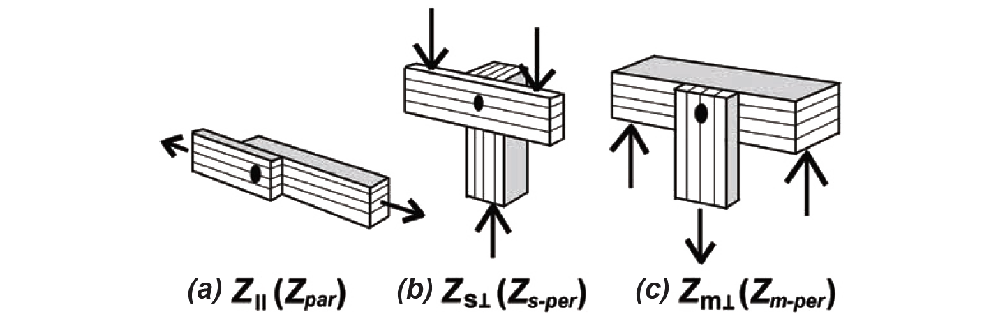
Aside from material properties for wood and steel, two other relationships between fastener and wood member must be accounted for: the penetration of lag screws and nails into the main member of the connection, as described in Appendix Table A-3.19; and the grain orientation of the various members being connected, with respect to the direction of load, as shown in Figure 3.32. To obtain full lateral design values, lag screw penetration must be at least equal to 8D, and nail penetration must be at least equal to 10D (where D is the fastener diameter).
Just as the allowable stresses for wood structural elements in tension, compression, or bending are adjusted to account for the actual behavioral properties of wood, the design values for wood fasteners are also adjusted in several ways. Two of these adjustments have already been discussed under the heading, material properties, although there are subtle differences in their application to fasteners. The duration of load factor (CD) accounts for changes in the strength of wood connections based on the length of time (duration) that the load is applied. However, because the yield limit equations used to analyze single- and double-shear connections can also be used where steel side members are combined with wood main members, the allowable stress for such steel members has been reduced by a factor of 1.6, corresponding to the maximum duration-of-load adjustment for wood members under wind or seismic loading. In this way, CD may be applied to the entire connection design (so that the steel stress, already reduced, is increased up to its actual value in cases where the load combination includes wind or seismic forces), simplifying the design process, although making the steel side-member design conservative for load combinations that do not include wind or seismic forces (since in those cases, the steel stress is still initially reduced, but not increased by the same amount).
The wet service factor (CM) accounts for the increased strength of wood when used "dry." For connection design, it is also important to consider the moisture content of the wood when it was first fabricated, since a change from an initial "wet" fabrication condition to a "dry" service condition can weaken the connection in some cases.
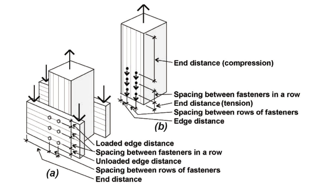
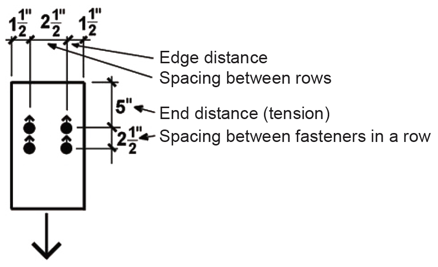
Two additional adjustments apply to dowel-type fasteners only, and only when the fastener diameter is greater or equal to 1/4 in. (i.e., for bolts and lag screws). The group action adjustment (Cg) accounts for reductions in strength that may occur when comparing the behavior of a single fastener to that of a group of fasteners; the geometry factor (CΔ) includes a series of possible reductions that come into play when fasteners are closely spaced, or are placed too close to the edge or end of a wood member, as shown in Figure 3.33. The orientation of the wood grain determines the "edge" and "end" of the members, irrespective of the load direction; whereas "row spacing" parameters are measured with respect to the direction of the load (a "row of fasteners" being parallel to the direction of load).
For nails only, a toe-nail factor adjustment, Ctn, is used for lateral or withdrawal design values (see Appendix Table A-3.24) when the side and main members are fastened with nails driven at a 30° angle to the face of the side member.
The general strategy for designing wood connections is to first find the capacity of a single fastener, using one of the strategies discussed (i.e., using yield limit equations, or various tabular design aids), and then to multiply that capacity by the number of fasteners comprising the connection. As already suggested, this total capacity for multiple fasteners is explicitly modified using the group action adjustment factor Cg; the other adjustments — CD, CM, and CΔ — can be applied to either the entire connection or just a single fastener, but should only be applied once each per connection. A temperature factor, Ct, should be applied to wood elements subjected to sustained high temperatures: see Appendix Table A-3.25.
The complete dowel-type fastener design process for wood elements is summarized below; this summary constitutes the "Solution overview" within the examples that follow (with steps 4 and 5 eliminated where the connection consists of a single fastener only):
1. Find the capacity for a single fastener, Z.
2. For lag screws and nails, check that penetration into the main member is at least 4D (for lag screws) or 6D (for nails), and adjust capacity, Z, accordingly.
3. Adjust for duration of load, wet service conditions, and geometry.
4. For multiple-fastener connections only, adjust for group action, and then multiply the adjusted single-fastener capacity by the number of fasteners in the connection.
5. Remember that in addition to the fasteners, the element itself must be designed in a manner that accounts for the presence of bolt or lag screw holes (nail holes are not considered in structural element design). For multiple-fastener connections only, and only where forces are parallel to grain and in tension, also check the element for row and group tear-out (discussed earlier under the heading, tension).
Tables for computing fastener capacity are included in the appendix at the end of this chapter; specific guidelines for the use of these tables are provided in the examples that follow.
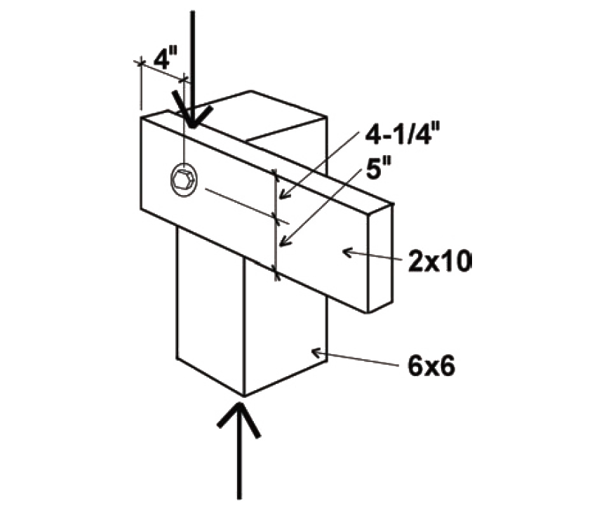
Problem definition. Find the capacity of a connection (single shear) consisting of a 2 × 10 beam connected to a 6 × 6 post using one 3/4 in. diameter bolt, as shown in Figure 3.34. The wood used is Hem-Fir, and the bolts are fabricated from ordinary, low-strength, A307 steel, as is typical for wood connections. Assume live and dead loads only, dry fabrication and service conditions, and spacing as shown.
Solution overview
1. Find the capacity for a single fastener, Z.
2. For lag screws and nails, check that penetration into the main member is at least 4D (for lag screws) or 6D (for nails), and reduce capacity, Z, if necessary.
3. Adjust for duration of load, moisture, and geometry.
4. Adjust for group action (not applicable for single fastener connections).
5. Check that the element itself is designed in a manner that accounts for the presence of bolt or lag screw holes (not included in this example).
Problem solution
1. From Appendix Table A-3.26, the lateral design value, Zs-per, is 460 lb. The value of Z chosen corresponds to the following condition: the side member (for bolted connections in single shear, the side member is defined as the thinner of the two members) is oriented so that the load is perpendicular to the direction of grain, while the main member is oriented so that the load is parallel to the direction of grain. This corresponds to Zs-per, as defined in Figure 3.32.
2. From Appendix Table A-3.19 (Note 4), penetration is only an issue with lag screws and nails, since bolts must always fully penetrate the members being connected. Therefore, no reduction of the tabular lateral design value is necessary, and it remains equal to Zs-per = 460 lb.
3. Adjustments are as follows:
CD for typical values of live and dead load is 1.0 (Appendix Table A-3.20).
CM for members fabricated and used "dry" is 1.0 (Appendix Table A-3.21).
Cg does not apply to single-fastener connections.
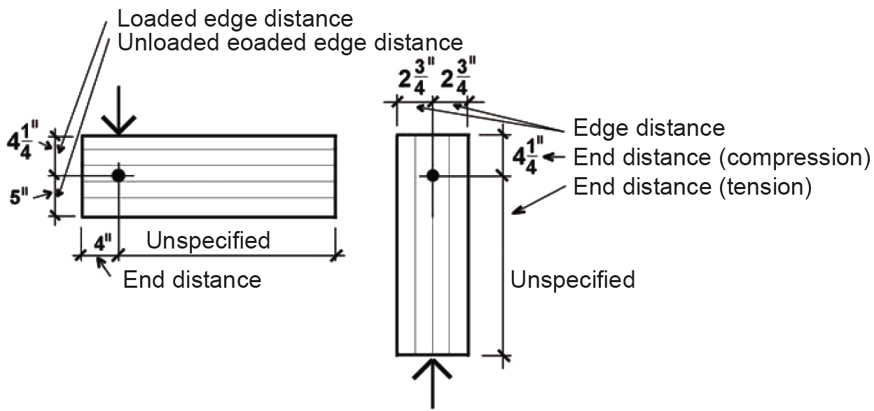
CΔ is found by testing four separate criteria (Appendix Table A-3.23): spacing between fasteners in a row (not applicable where only one fastener is used); spacing between rows of fasteners (not applicable where only one fastener is used); end distance; and edge distance. It is sometimes useful to sketch the members separately, showing dimensions for the relevant geometry factor parameters (Figure 3.35). In the calculations that follow, the fastener diameter is: D = 3/4 in. = 0.75 in.
Spacing criteria: For a single fastener connection, the spacing criteria (for spacing between rows and spacing of fasteners within a row) do not apply.
End distance: Adjustment criteria for end distance appear in Appendix Table A-3.23, part C. For the horizontal member, the loading direction is perpendicular to grain, so the minimum end distance for full value (i.e., for CΔ = 1.0) is 4D = 4 × 0.75 = 3 in. Since the actual end distance of 4 in. exceeds this value (and the other, unspecified, end distance is clearly larger), the geometry factor, CΔ = 1.0 for horizontal member end distance. For the vertical member, the loading direction is parallel to grain and the specified wood is a "softwood," so the minimum end distance for full value for "tension" (i.e., for CΔ = 1.0) is 7D = 7 × 0.75 = 5.25 in. Since the actual end distance, although unspecified, clearly exceeds this, the geometry factor, CΔ = 1.0 for vertical member end distance (tension). For the full value in "compression," we need a minimum end distance of 4D = 4 × 0.75 = 3 in., which the actual end distance of 4-1/4 in. exceeds. The geometry factor therefore is also CΔ = 1.0 for vertical member end distance (compression).
Edge distance: Adjustment criteria for edge distance appear in Appendix Table A-3.23, part D. For the horizontal member, the loading direction is perpendicular to grain, so the loaded and unloaded edges must be determined separately. The minimum distance for the loaded edge (i.e., the edge towards which the fastener itself is bearing) is 4D = 4 × 0.75 = 3 in., which the actual loaded edge distance of 4-1/4 in. exceeds. The minimum distance for the unloaded edge (i.e., the opposite edge away from which the fastener itself is bearing) is 1.5D = 1.5 × 0.75 = 1.125 in., which the actual unloaded edge distance of 5 in. exceeds. For the vertical member, the loading direction is parallel to grain, so the minimum edge distance is determined from the so-called slenderness ratio of the fastener, l/D. The length of the fastener, l, within the main member is 5-1/2 in., so l/D = 5.5/0.75 = 7.33. Since this value is greater than 6, the minimum edge distance is 1.5D = 1.5 × 0.75 = 1.125 in., which the actual edge distance of 2.75 in. exceeds. Since all the criteria for full value are met, the geometry factor for edge distance is CΔ = 1.0.
The geometry factor for the entire connection is found by using the smallest of the geometry factors found for any of the four conditions tested above (end, edge, and the two spacing conditions where applicable): therefore, we use CΔ = 1.0.
The adjusted lateral design value for the single fastener in the connection is found by multiplying the lateral design value from step 2 by the various adjustment factors determined in step 3: Z' = Z(CD)(CM)(CΔ) = 460(1.0)(1.0)(1.0) = 460 lb.
4. The group action factor, Cg, is 1.0 for all single-fastener connections (since only multiple fastener connections can have "group action"). Therefore, the connection capacity is equal to Z' (Cg) = 460(1.0) = 460 lb.
5. We are not considering the design of the structural elements themselves in this example.
6. Conclusion: The total capacity of the connection (consisting of a single 3/4 in. diameter bolt) is 460 lb.
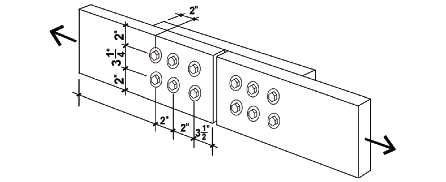
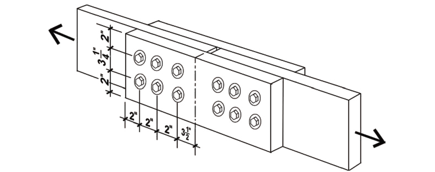
Problem definition. Find the capacity of a connection (single shear) consisting of two 2 × 8 tension elements connected by a 2 × 8 member using six ½ in. diameter bolts in each member. The wood used is Hem-Fir No. 1, and the bolts are fabricated from ordinary, low-strength, A307 steel, as is typical for wood connections. Assume live, dead, and wind loads only, dry fabrication and service conditions, and spacing as shown in Figure 3.36.
Solution overview
1. Find the capacity for a single fastener, Z.
2. For lag screws and nails, check that penetration into the main member is at least 4D (for lag screws) or 6D (for nails), and reduce capacity, Z, if necessary.
3. Adjust for duration of load, moisture, and geometry.
4. Adjust for group action, and then multiply the adjusted single-fastener capacity by the number of fasteners in the connection.
5. Check that the element itself is designed in a manner that accounts for the presence of bolt or lag screw holes (not included in this example).
Problem solution
1. From Appendix Table A-3.26, the lateral design value, Zpar, is 410 lb. The value of Z chosen corresponds to the following condition: both the side and main member are oriented so that the load is parallel to the direction of grain, as defined in Figure 3.32.
2. From Appendix Table A-3.19 (Note 4), penetration is only an issue with lag screws and nails, since bolts must always fully penetrate the members being connected. Therefore, no reduction of the tabular lateral design value is necessary, and it remains equal to Zpar = 410 lb.
3. Adjustments are as follows:
CD for live, dead, and wind load is 1.6 (Appendix Table A-3.20);
CM for members fabricated and used "dry" is 1.0 (Appendix Table A-3.21);
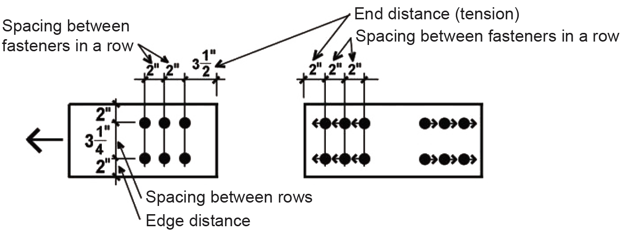
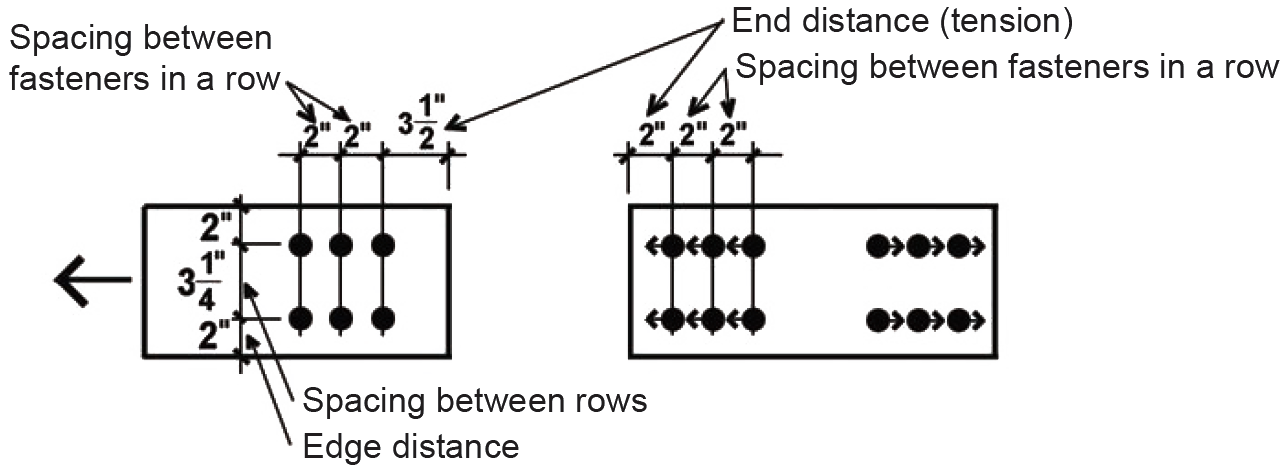
CΔ is found by testing four separate criteria (Appendix Table A-3.23): spacing between fasteners in a row; spacing between rows of fasteners; end distance; and edge distance. It is sometimes useful to sketch the members separately, showing dimensions for the relevant geometry factor parameters (Figure 3.37):
In the calculations that follow, D is the fastener diameter of 1/2 in.
Spacing criteria: Adjustment criteria for spacing appear in Appendix Table A-3.23, parts A and B. For spacing between fasteners in a row, where the loading direction is parallel to grain, the minimum spacing for full value is 4D = 4 × 0.5 = 2 in. Since the actual spacing is 2 in., the full value applies, and CΔ = 1.0 for spacing between fasteners in a row. For spacing between rows of fasteners, again with the loading direction parallel to grain, the minimum required spacing is 1.5D = 1.5 × 0.5 = 0.75 in. Since the actual spacing (between rows) of 3.25 in. exceeds this value, and is no greater than 5 in. (the maximum distance allowed between the outer rows of fasteners), the geometry factor is CΔ = 1.0 for spacing between rows of fasteners.
End distance: Adjustment criteria for end distance appear in Appendix Table A-3.23, part C. For all the members, the loading direction is parallel to grain. Where the fasteners are bearing towards the member end (in "tension") and where the wood is "softwood," the minimum end distance for full value (i.e., for CΔ = 1.0) is 7D = 7 × 0.5 = 3.5 in. For the primary members, the actual end distance of 3.5 in. is no less than this, so the geometry factor, CΔ = 1.0. However, for the connecting member, shown to the right in Figure 3.37, the actual distance of 2 in. is between the absolute minimum (3.5D = 1.75 in.) and the required distance for full value (7D = 3.5 in.); therefore the geometry factor is taken as the actual end distance divided by the minimum distance for full value, or CΔ = 2/3.5 = 0.571.
Edge distance: Adjustment criteria for edge distance appear in Appendix Table A-3.23, part D. For all the members, the loading direction is parallel to grain, so the minimum edge distance is determined from the so-called slenderness ratio of the fastener, l/D. The length of the fastener, l, within all members is 1-1/2 in., so l/D = 1.5/0.5 = 3.0. Since this value is less than or equal to 6, the minimum edge distance is 1.5D = 1.5 × 0.5 = 0.75 in., which the actual edge distance of 2.0 in. exceeds. The geometry factor for edge distance is therefore CΔ = 1.0.
The geometry factor for the entire connection is found by using the smallest of the geometry factors found for any of the four conditions tested above (end, edge, and the two spacing conditions where applicable): therefore, we use CΔ = 0.571, which was computed for the end distance of the connecting member.
The adjusted lateral design value for a single bolt in the connection is found by multiplying the lateral design value from step 2 by the various adjustment factors determined in step 3: Z' = Z(CD)(CM)(CΔ) = 410(1.6)(1.0)(0.571) = 374.6 lb.
4. From Appendix Table A-3.22, the group action factor, Cg, is 0.993, a conservative value based on 2 × 8 main and side members (Am = As = approximately 11 in2), with three fasteners in a single row. The actual modulus of elasticity (Appendix Table A-3.9) for Hem-Fir No.1 is E = 1,500,000 psi, which is larger than the nominal value of 1,400,000 psi assumed in Appendix Table A-3.22; the actual fastener spacing, s = 2 in., is smaller than the value, s = 3 in., assumed in the table, and the actual fastener diameter, D = 1/2 in., is smaller than the value, D = 3/4 in., assumed in the table. Therefore, the tabular value, Cg = 0.993, is conservative and can be used. Alternatively, a more accurate value for Cg can be found, based on the method described in Note 3 of Appendix Table A-3.22, and illustrated in Example 3.15.
Adjusting for group action and multiplying the single-fastener value for Z' found in step 3 by the number of fasteners in the connection, we get a total adjusted connection capacity equal to 374.6(0.993)(6) = 2232 lb.
5. We are not considering the design of the structural elements themselves in this example. Tension, row and group tear-out are considered in Example 3.1.
6. Conclusion: The total capacity of the connection (consisting of a six 1/2 in. diameter bolts) is 2232 lb.
Problem definition. Find the capacity of a connection (double shear) consisting of two 2 × 8 tension elements connected by two shorter 2 × 8 members, using six 1/2 in. diameter bolts in each member. The wood used is Hem-Fir No.1, and the bolts are fabricated from ordinary, low-strength, A307 steel, as is typical for wood connections. Assume live, dead, and wind loads only, dry fabrication and service conditions, and spacing as shown in Figure 3.38.
Solution overview
1. Find the capacity for a single fastener, Z.
2. For lag screws and nails, check that penetration into the main member is at least 4D (for lag screws) or 6D (for nails), and reduce capacity, Z, if necessary.
3. Adjust for duration of load, moisture, and geometry.
4. Adjust for group action, and then multiply the adjusted single-fastener capacity by the number of fasteners in the connection.
5. Not included in this example (check that the element itself is designed in a manner that accounts for the presence of bolt or lag screw holes).
Problem solution
1. From Appendix Table A-3.27, the lateral design value, Zpar, is 900 lb. The value of Z chosen corresponds to the following condition: both the side and main member are oriented so that the load is parallel to the direction of grain, as defined in Figure 3.32.
2. From Appendix Table A-3.19 (Note 4), penetration is only an issue with lag screws and nails, since bolts must always fully penetrate the members being connected. Therefore, no reduction of the tabular lateral design value is necessary, and it remains equal to Zpar= 900 lb.
3. Adjustments are as follows:
CD for live, dead, and wind load is 1.6 (Appendix Table A-3.20);
CM for members fabricated and used "dry" is 1.0 (Appendix Table A-3.21);
CΔ is found by testing four separate criteria (Appendix Table A-3.23): spacing between fasteners in a row; spacing between rows of fasteners; end distance; and edge distance. It is sometimes useful to sketch the members separately, showing dimensions for the relevant geometry factor parameters (Figure 3.39).
In the calculations that follow, D is the fastener diameter of 1/2 in.
Spacing criteria: Adjustment criteria for spacing appear in Appendix Table A-3.23, parts A and B. For spacing between fasteners in a row, where the loading direction is parallel to grain, the minimum spacing for full value is 4D = 4 × 0.5 = 2 in. Since the actual spacing is 2 in., the full value applies, and CΔ = 1.0. For spacing between rows of fasteners, again with the loading direction parallel to grain, the minimum required spacing is 1.5D = 1.5 × 0.5 = 0.75 in. Since the actual spacing (between rows) of 3.25 in. exceeds this value, and is no greater than 5 in. (the maximum distance allowed between the outer rows of fasteners), the geometry factor is CΔ = 1.0.
End distance Adjustment criteria for end distance appear in Appendix Table A-3.23, part C. For all the members, the loading direction is parallel to grain. Where the fasteners are bearing towards the member end, i.e., in "tension" and for "softwood," the minimum end distance for full value (i.e., for CΔ = 1.0) is 7D = 7 × 0.5 = 3.5 in. For the main members, the actual end distance of 3.5 in. is no less than this, so the geometry factor, CΔ = 1.0. However, for the connecting member, shown to the right in Figure 3.39, the actual distance of 2 in. is between the absolute minimum (3.5D = 1.75 in.) and the required distance for full value (7D = 3.5 in.); therefore the geometry factor is taken as the actual end distance divided by the minimum distance for full value, or CΔ = 2/3.5 = 0.571.
Edge distance Adjustment criteria for edge distance appear in Appendix Table A-3.23, part D. For all the members, the loading direction is parallel to grain, so the minimum edge distance is determined from the so-called slenderness ratio of the fastener, l/D. The fastener length, l, within all members is 1-1/2 in., so l/D = 1.5/0.5 = 3.0. Since this value is less than or equal to 6, the minimum edge distance is 1.5D = 1.5 × 0.5 = 0.75 in., which the actual edge distance of 2.0 in. exceeds. The geometry factor therefore is CΔ = 1.0.
The geometry factor for the entire connection is found by using the smallest of the geometry factors found for any of the four conditions tested above (end, edge, and the two spacing conditions where applicable): therefore, we use CΔ = 0.571, which was computed for the end distance of the connecting member.
The adjusted lateral design value for a single bolt in the connection is found by multiplying the lateral design value from step 2 by the various adjustment factors determined in step 3: Z' = Z(CD)(CM)(CΔ) = 900(1.6)(1.0)(0.571) = 822.2 lb.
4. From Appendix Table A-3.22, the group action factor, Cg , is 0.983, a conservative value based on a single 2 × 8 main member and two 2 × 8 side members (Am = approximately 11 in2; As = approximately 17 in2), with three fasteners in a single row. The actual modulus of elasticity (Appendix Table A-3.9) for Hem-Fir No.1 is E = 1,500,000 psi, which is larger than the nominal value of 1,400,000 psi assumed in the table; the actual fastener spacing, s = 2 in., is smaller than the value, s = 3 in., assumed in the table, and the actual fastener diameter, D = 1/2 in., is smaller than the value, D = 3/4 in., assumed in the table; therefore, the tabular value, Cg = 0.983, is conservative and can be used. Alternatively, a more accurate value for Cg can be found, based on the method described in Note 3 of Appendix Table A-3.22, and illustrated in Example 3.15. Adjusting for group action and multiplying the single-fastener value for Z' found in step 3 by the number of fasteners in the connection, we get a total adjusted connection capacity equal to 822.2(0.983)(6) = 4849 lb.
5. We are not considering the design of the structural elements themselves in this example. Tension, row and group tear-out are considered in Example 3.1.
6. Conclusion: The total capacity of the connection (consisting of a six 1/2 in. diameter bolts) is 4849 lb.
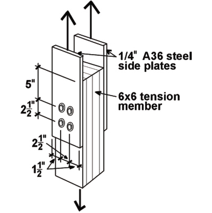
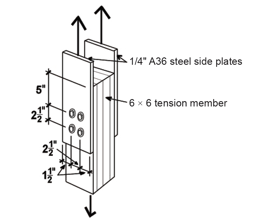
Problem definition. Find the capacity of a connection (double shear) consisting of a 6 × 6 tension member connected by two 1/4 in. steel side plates, using four 5/8 in. diameter bolts. The wood used is Douglas Fir-Larch (North) No. 1, the steel plates are ASTM A36 steel, and the bolts are fabricated from ordinary, low-strength, A307 steel, as is typical for wood connections. Assume live and dead loads only, dry fabrication and service conditions, and spacing as shown in Figure 3.40.
Solution overview
1. Find the capacity for a single fastener, Z.
2. For lag screws and nails, check that penetration into the main member is at least 4D (for lag screws) or 6D (for nails), and reduce capacity, Z, if necessary.
3. Adjust for duration of load, moisture, and geometry.
4. Adjust for group action, and then multiply the adjusted single-fastener capacity by the number of fasteners in the connection.
5. Not included in this example (check that the element itself is designed in a manner that accounts for the presence of bolt or lag screw holes).
Problem solution
1. From Appendix Table A-3.28, the lateral design value, Zpar, is 2390 lb. The value of Z chosen corresponds to the following condition: the main member is oriented so that the load is parallel to the direction of grain, as defined in Figure 3.32. The orientation of the steel side plates to the direction of load is not relevant, since there is no "grain" in the steel plates that influences its strength.
2. From Appendix Table A-3.19 (Note 4), penetration is only an issue with lag screws and nails, since bolts must always fully penetrate the members being connected. Therefore, no reduction of the tabular lateral design value is necessary, and it remains equal to Zpar = 2390 lb.
3. Adjustments are as follows:
CD for typical values of live and dead load is 1.0 (Appendix Table A-3.20);
CM for members fabricated and used "dry" is 1.0 (Appendix Table A-3.21);
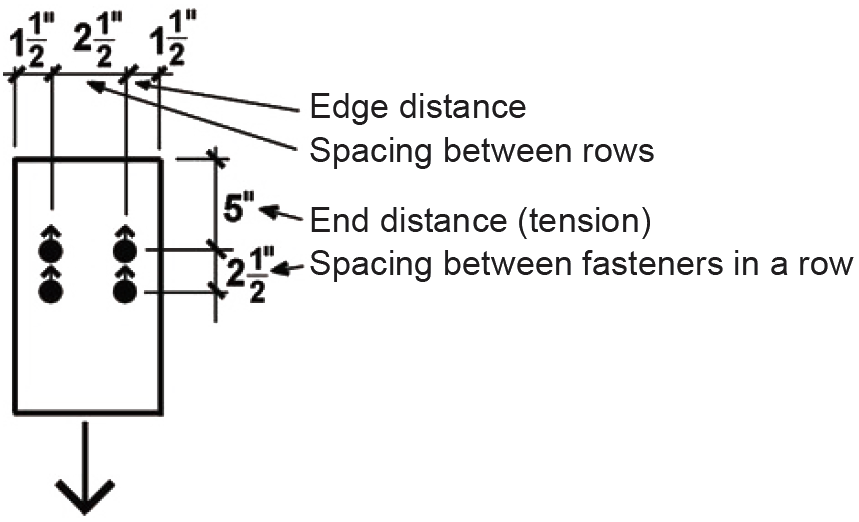
CΔ is found by testing four separate criteria (Appendix Table A-3.23): spacing between fasteners in a row; spacing between rows of fasteners; end distance; and edge distance. It is sometimes useful to sketch the members separately, showing dimensions for the relevant geometry factor parameters (Figure 3.41). Only the wood main member is considered here; the tension capacity and bolt spacing in the steel plate must be considered separately (see Chapter 4 for discussion of steel subjected to tension and for discussion of bolt spacing).
In the calculations that follow, D is the fastener diameter of 5/8 in. = 0.625 in.
Spacing criteria: Adjustment criteria for spacing appear in Appendix Table A-3.23, parts A and B. For spacing between fasteners in a row, where the loading direction is parallel to grain, the minimum spacing for full value is 4D = 4 × 0.625 = 2.5 in. Since the actual spacing is 2.5 in., the full value applies, and CΔ = 1.0. For spacing between rows of fasteners, again with the loading direction parallel to grain, the minimum required spacing is 1.5D = 1.5 × 0.625 = 0.9375 in. Since the actual spacing (between rows) of 2.5 in. exceeds this value, and is no greater than 5 in. (the maximum distance allowed between the outer rows of fasteners), the geometry factor is CΔ = 1.0.
End distance: Adjustment criteria for end distance appear in Appendix Table A-3.23, part C. For the main member, the loading direction is parallel to grain. Where the fasteners are bearing toward the member end (in "tension") and where the wood is "softwood," the minimum end distance for full value (i.e., for CΔ = 1.0) is 7D = 7 × 0.625 = 4.375 in. The actual end distance of 5 in. is greater than this, so the geometry factor, CΔ = 1.0.
Edge distance: Adjustment criteria for edge distance appear in Appendix Table A-3.23, part D. For the main member, the loading direction is parallel to grain, so the minimum edge distance is determined from the so-called slenderness ratio of the fastener, l/D. The fastener length, l, within the main member is 5-1/2 in., so l/D = 5.5/0.625 = 8.8. Since this value is greater than 6, the minimum edge distance is either 1.5D = 1.5 × 0.625 = 0.9375 in., or one half of the spacing between rows = 0.5 × 2.5 = 1.25 in., whichever is greater: the minimum edge distance is therefore 1.25 in., which the actual edge distance of 1.5 in. exceeds. The geometry factor therefore is CΔ = 1.0.
The geometry factor for the entire connection is found by using the smallest of the geometry factors found for any of the four conditions tested above (end, edge, and the two spacing conditions where applicable): therefore, we use CΔ = 1.0.
The adjusted lateral design value for a single bolt in the connection is found by multiplying the lateral design value from step 2 by the various adjustment factors determined in step 3: Z' = Z(CD)(CM)(CΔ) = 2390(1.0)(1.0)(1.0) = 2390 lb.
4. From Appendix Table A-3.22 (part B for steel side members) the group action factor, Cg, is 0.997, a conservative value based on a 6 × 6 main member and two 1/4 in. steel side plates (Am = approximately 30 in2; As approximately 3 in2), with two fasteners in a single row. The actual modulus of elasticity (Appendix Table A-3.9) for Douglas Fir-Larch (North) No.1 is E = 1,600,000 psi (for "posts and timbers"), which is larger than the nominal value of 1,400,000 psi assumed in the table; the actual fastener spacing, s = 2.5 in., is smaller than the value, s = 3 in., assumed in the table, and the actual fastener diameter, D = 5/8 in., is smaller than the value, D = 3/4 in., assumed in the table; therefore, the tabular value, Cg = 0.997, is conservative and can be used. Alternatively, a more accurate value for Cg can be found, based on the method described in Note 3 of Appendix Table A-3.22, and illustrated in Example 3.15.
Adjusting for group action and multiplying the single-fastener value for Z' found in step 3 by the number of fasteners in the connection, we get a total adjusted connection capacity equal to 2390(0.997)(4) = 9531 lb.
5. We are not considering the design of the structural elements themselves in this example. Tension, row and group tear-out are considered in Example 3.1.
6. Conclusion: The total capacity of the connection (consisting of a four 5/8 in. diameter bolts) is 9531 lb.
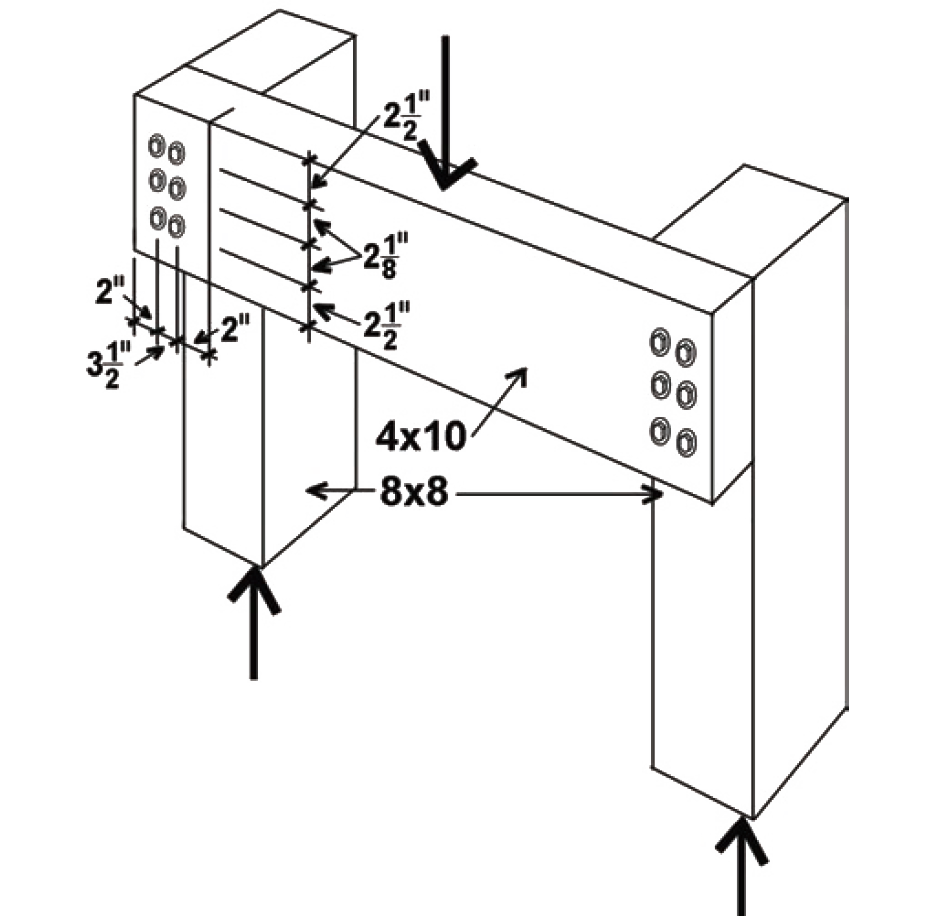
Problem definition. Find the capacity of a connection (single shear) consisting of a 4 × 10 beam connected to an 8 × 8 post using six 6-in.-long, 1/2-in.-diameter lag screws. The wood used is Douglas Fir-Larch No.2, and the lag screws are fabricated from ordinary, low-strength, A307 steel. Assume live and dead loads only, dry fabrication and service conditions, and spacing as shown in Figure 3.42.
Solution overview
1. Find the capacity for a single fastener, Z.
2. For lag screws and nails, check that penetration into the main member is at least 4D (for lag screws) or 6D (for nails), and reduce capacity, Z, if necessary.
3. Adjust for duration of load, moisture, and geometry.
4. Adjust for group action, and then multiply the adjusted single-fastener capacity by the number of fasteners in the connection.
5. Not included in this example (check that the element itself is designed in a manner that accounts for the presence of bolt or lag screw holes).
Problem solution
1. From Appendix Table A-3.29, the lateral design value, Zs-per, is 270 lb. The value of Z chosen corresponds to the following condition: the side member is oriented so that the load is perpendicular to the direction of grain, while the main member is oriented so that the load is parallel to its grain, as defined in Figure 3.32.
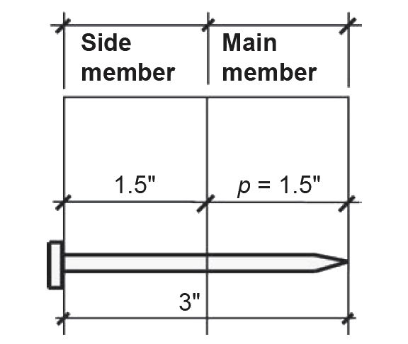
2. Penetration must be checked for lag screws (see Appendix Table A-3.19 for notes on penetration; lag screw dimensions can be found in Appendix Table A-3.17). The actual penetration, p = 2.1875 in., can be found by first subtracting the side member thickness of 3.5 in. from the lag screw length, L = 6 in., to get 2.5 in.; and then subtracting the length of the tapered tip, E = 0.3125 in., from the 2.5 in. length within the main member, as illustrated in Figure 3.43.
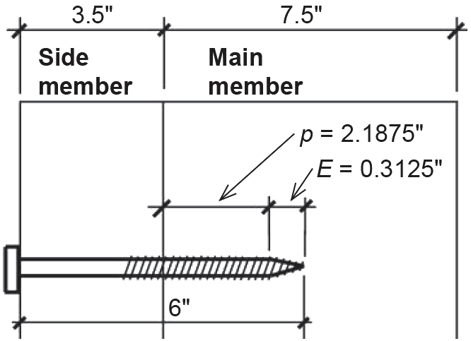
This actual penetration is then compared to the minimum lengths for lag screw penetration in Appendix Table A-3.19: the absolute minimum is 4D = 4 × 0.5 = 2 in.; the minimum penetration to obtain the full value of Z is 8D = 8 × 0.5 = 4 in. Since the actual penetration is between these two values, the lateral design value, Z, is reduced by multiplying it by p/(8D) = 2.1875/4 = 0.547. Therefore, we use a lateral design value of 270 × 0.547 = 148 lb.
3. Adjustments are as follows:
CD for typical values of live and dead load is 1.0 (Appendix Table A-3.20);
CM for members fabricated and used "dry" is 1.0 (Appendix Table A-3.21);
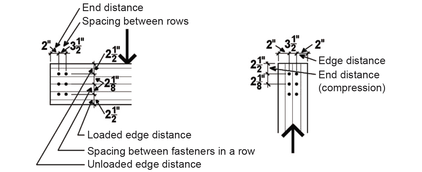
CΔ is found by testing four separate criteria (Appendix Table A-3.23): spacing between fasteners in a row; spacing between rows of fasteners; end distance; and edge distance. It is sometimes useful to sketch the members separately, showing dimensions for the relevant geometry factor parameters (Figure 3.44):
In the calculations that follow, D is the fastener diameter of 1/2 in. (however, for lag screws, the so-called reduced body diameter, Dr = 0.371 in., is used to calculate lateral design values).
Spacing criteria: Adjustment criteria for spacing appear in Appendix Table A-3.23, parts A and B. For spacing between fasteners in a row for the horizontal member, where the loading direction is perpendicular to grain, the minimum spacing for full value is determined by the required values for the attached member (i.e., for the vertical member with loading parallel to grain). For spacing between rows of fasteners, again with the loading direction perpendicular to grain, the minimum required spacing is determined from the so-called slenderness ratio of the fastener, l/D. For lag screws, the dowel bearing length equals the penetration within the main member found in step 2, as noted in Appendix Table A-3.19. Therefore, the dowel bearing length, l, equals 2.1875 in., and l/D = 2.1875/0.5 = 4.375. Since this value is between 2 and 6, the minimum spacing between rows of fasteners is (5l + 10D)/8 = (5 × 2.1875 + 10 × 0.5) /8 = 1.992 in., which the actual spacing between rows of 3.5 in. exceeds. Therefore, the geometry factor is CΔ = 1.0.
For spacing between fasteners in a row, where the loading direction is parallel to grain, the minimum spacing for full value is 4D = 4 × 0.5 = 2 in. Since the actual spacing is 2-1/8 in., the full value applies here (and also to the horizontal member), and CΔ = 1.0. For spacing between rows of fasteners, again with the loading direction parallel to grain, the minimum required spacing is 1.5D = 1.5 × 0.5 = 0.75 in. Since the actual spacing (between rows) of 3.5 in. exceeds this value, and is no greater than 5 in. (the maximum distance allowed between the outer rows of fasteners), the geometry factor is CΔ = 1.0.
End distance: Adjustment criteria for end distance appear in Appendix Table A-3.23, part C. For the horizontal member, the loading direction is perpendicular to grain, so the minimum end distance for full value (i.e., for CΔ = 1.0) is 4D = 4 × 0.5 = 2 in. Since the actual end distance of 2 in. equals this value (and the other, unspecified, end distance is clearly larger), the geometry factor, CΔ = 1.0. For the vertical member, the loading direction is parallel to grain and the specified wood is a "softwood," so the minimum end distance for full value for "tension" (i.e., for CΔ = 1.0) is 7D = 7 × 0.5 = 3.5 in. Since the actual end distance, although unspecified, clearly exceeds this, the geometry factor, CΔ = 1.0. For the full value in "compression," we need a minimum end distance of 4D = 4 × 0.5 = 2 in., which the actual end distance of 2-1/2 in. exceeds. The geometry factor therefore is also CΔ = 1.0.
Edge distance: Adjustment criteria for edge distance appear in Appendix Table A-3.23, part D. For the horizontal member, the loading direction is perpendicular to grain, so the loaded and unloaded edges must be determined separately. The minimum distance for the loaded edge (i.e., the edge towards which the fastener itself is bearing) is 4D = 4 × 0.5 = 2 in., which the actual loaded edge distance of 2-1/2 in. exceeds. The minimum distance for the unloaded edge (i.e., the opposite edge away from which the fastener itself is bearing) is 1.5D = 1.5 × 0.5 = 0.75 in., which the actual unloaded edge distance of 2½ in. exceeds. For the vertical member, the loading direction is parallel to grain, so the minimum edge distance is determined from the so-called slenderness ratio of the fastener, l/D. The dowel bearing length, l, within the main member is 2.1875 in., so l/D = 2.1875/0.5 = 4.375. Since this value is less than or equal to 6, the minimum edge distance is 1.5D = 1.5 × 0.5 = 0.75 in., which the actual edge distance of 2.0 in. exceeds. The geometry factor therefore is CΔ = 1.0.
The geometry factor for the entire connection is found by using the smallest of the geometry factors found for any of the four conditions tested above (end, edge, and the two spacing conditions where applicable): therefore, we use CΔ = 1.0.
The adjusted lateral design value for a single lag screw in the connection is found by multiplying the lateral design value from step 2 by the various adjustment factors determined in step 3: Z' = Z(CD)(CM)(CΔ) = 148(1.0)(1.0)(1.0) = 148 lb.4. From Appendix Table A-3.22, the group action factor, Cg , is 0.970, a conservative value based on an 8 × 8 main member and a side member with an effective area of 12.25 in2 (because the side member is loaded perpendicular to grain, its effective area is taken as its thickness of 3.5 in. multiplied by the distance between the outer rows of fasteners, also 3.5 in.). For use in Appendix Table A-3.22, these areas are rounded as follows: Am = 56 in2 and As = 11 in2. The actual modulus of elasticity (Appendix Table A-3.9) for Hem-Fir No.1 is E = 1,500,000 psi, which is larger than the nominal value of 1,400,000 psi assumed in the table; the actual fastener spacing, s = 2 in., is smaller than the value, s = 3 in., assumed in the table, and the actual fastener diameter, D = 1/2 in., is smaller than the value, D = 3/4 in., assumed in the table; therefore, the tabular value, Cg = 0.970, is conservative and can be used. Alternatively, a more accurate value for Cg can be found, based on the method described in Note 3 of Appendix Table A-3.22, and illustrated in Example 3.15.
Adjusting for group action (using Cg = 0.970), and multiplying the single-fastener value for Z' found in step 3 by the number of fasteners in the connection, we get a total adjusted connection capacity equal to 148(0.970)(6) = 861 lb.
5. We are not considering the design of the structural elements themselves in this example.
6. Conclusion: The total capacity of the connection (consisting of a six 1/2 × 6 in. lag screws) is 861 lb.
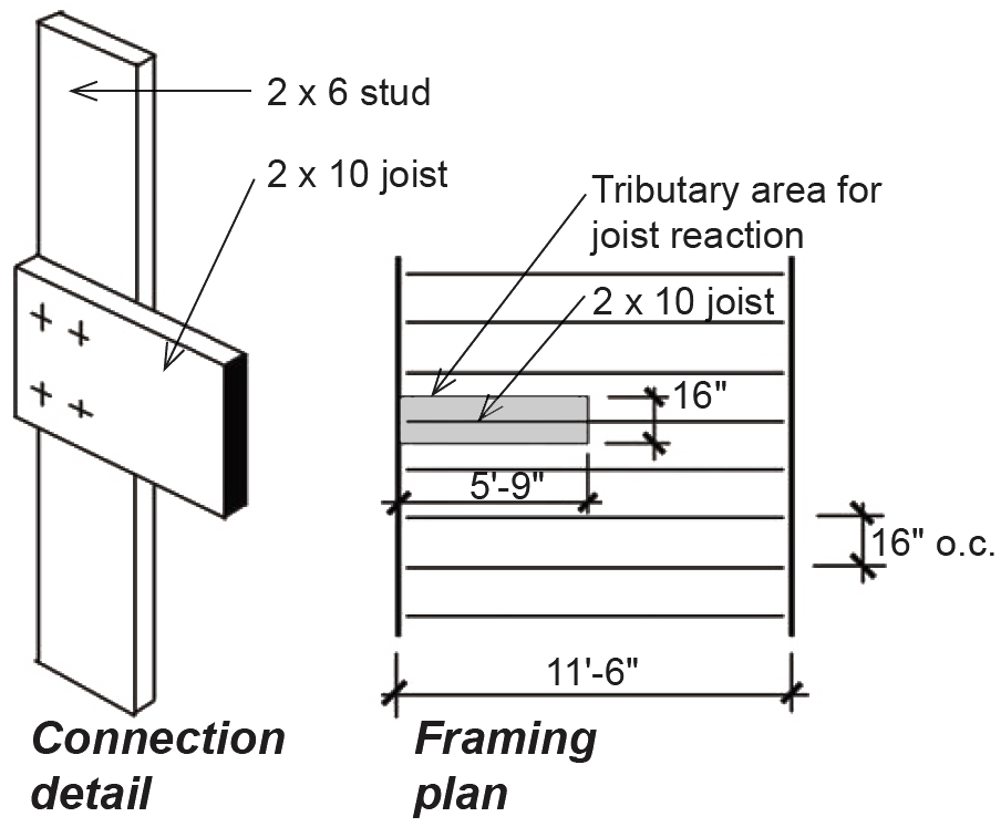
Problem definition. Determine the number of 10d common nails needed to connect a typical 2 × 10 floor joist, spanning 11.5 ft and spaced at 16 in. on center, to a 2 × 6 stud, as shown in Figure 3.45. The wood used is Spruce-Pine-Fir No.1/No.2, the distributed loads on the floor consist of 40 psf live load and 10.5 psf dead load, and the wood is fabricated and used "dry."
Solution overview
1. Find the capacity for a single fastener, Z.
2. For lag screws and nails, check that penetration into the main member is at least 4D (for lag screws) or 6D (for nails), and reduce capacity, Z, if necessary.
3. Adjust for duration of load, moisture, and geometry.
4. Group action does not apply to nailed connections.
5. Check that the element itself is designed in a manner that accounts for the presence of bolt or lag screw holes (not applicable).
6. Find the total force acting on the connection and divide by the adjusted capacity for a single fastener to find the number of fasteners required.
Problem solution
1. From Appendix Table A-3.30, the lateral design value, Z, is 100 lb, for a 10d nail and a 1-1/2 in. side member.
2. In general, penetration must be checked for nails (see Appendix Table A-3.19): however, tabular values in Appendix Table A-3.30 already include reductions for penetration, so this step is only necessary when lateral design values are computed using other means. We can confirm that a penetration reduction is not necessary by computing the actual penetration, p = 1-1/2 in., as shown in Figure 3.46. First, subtract the side member thickness of 1-1/2 in. from the nail length of 3 in., to get 1-1/2 in. (nail dimensions can be found in Appendix Table A-3.18).
Next, the actual penetration is compared to the minimum requirements for nail penetration in Appendix Table A-3.19. Since p = 1.5 in. ≥ 10D = 10 × 0.148 = 1.48 in., we can use the full lateral design value. For values of p < 10D, lateral capacity would need to be reduced by p/(10d). In all cases where yield limit equations are used for nails, the dowel bearing length in the main member, lm, is taken as the penetration minus half the length of the tapered tip, so that tabular lateral design values, which do not consider this reduced dowel bearing length, may be slightly nonconservative in some cases (specifically, they may differ in cases where the governing yield limit equation includes the dowel bearing length parameter).
The lateral design value, Z, remains 100 lb.
3. Adjustments are as follows:
CD for live and dead load is 1.0 (Appendix Table A-3.20);
CM for members fabricated and used "dry" is 1.0 (Appendix Table A-3.21);
CΔ = 1.0 for dowel-type fasteners with D < 1/4 in. This applies to virtually all nails, certainly for 10d nails with D = 0.148 in. (see Appendix Table A-3.18). While no specific numerical requirements are given for nail spacing, and edge or end distances, nails should be configured so that splitting of the wood members does not occur.
The adjusted lateral design value for the connection is found by multiplying the lateral design value from step 2 by the various adjustment factors determined in step 3: Z' = Z(CD)(CM)(CΔ) = 100(1.0)(1.0)(1.0) = 100 lb.
4. The group action factor, Cg = 1.0, for fasteners with diameter, D < 1/4 in., i.e., for most nailed connections.
5. We are not considering the design of the structural elements themselves in this example.
6. To determine the number of nails needed, we first find the total force acting at the connection, i.e., the reaction of a typical joist, by multiplying the floor loads by the tributary area for half of a single joist: (40 + 10.5)(5.75 × 1.33) = 387.2 lb. Dividing this total force by 100 lb (the capacity of a single fastener), we get the required number of fasteners, n = 387.2/100 = 3.87; i.e., we need four 10d nails.
Problem definition. Find the capacity of a connection (double shear) consisting of a 6 × 6 tension member connected by two 1/4 in. steel side plates, using four 5/8 in. diameter bolts. The wood used is Douglas Fir-Larch (North) No. 1, the side plates are ASTM A36 steel, and the bolts are fabricated from ordinary, low-strength, A307 steel, as is typical for wood connections. Assume live and dead loads only, dry fabrication and service conditions, and spacing as shown in Figure 3.47. Use yield limit and group action equations, rather than tabular values (see Example 3.12 for solution using tabular values).
Solution overview
1. Find the capacity for a single fastener, Z, using yield limit equations.
2. For lag screws and nails, check that penetration into the main member is at least 4D (for lag screws) or 6D (for nails), and reduce capacity, Z, if necessary.
3. Adjust for duration of load, moisture, and geometry.
4. Adjust for group action using group action factor equations, and then multiply the adjusted single-fastener capacity by the number of fasteners in the connection.
5. Check that the element itself is designed in a manner that accounts for the presence of bolt or lag screw holes (not included in this example).
Problem solution
1. To find the lateral design value, Z, for a single fastener using yield limit equations, follow the step-by-step method outlined in Appendix Table A-3.31. The main member is oriented so that the load is parallel to the direction of grain, as defined in Figure 3.32. The orientation of the steel side plates to the direction of load is not relevant, since there is no "grain" in a steel plate that influences its strength.
a. From Appendix Table A-3.11, G = 0.49 for Douglas Fir-Larch (North).
b. D = 5/8 in. = 0.625 in.
c. Main member (D > 0.25 in., wood, loaded parallel to grain):
Fem = 11,200G = 11,200 × 0.49 = 5488 psi. Side member (A36 steel):
Fes = 87,000 psi. It is common to round these values to the nearest 50 psi, so we will use
Fem = 5500 psi.
d. Fyb = 45,000 psi for bolts.
e. Dowel bearing lengths are lm = 5.5 in. and ls = 0.25 in.
f. Compute the terms Re = Fem/Fes = 5500/87,000 = 0.06322; and Rt = lm/ls = 5.5/0.25 = 22.0.
g. Rd = 4 Kθ = 4(1.0) = 4 (for yield modes Im and Is); Rd = 3.6Kθ = 3.6(1.0) = 3.6 (for yield mode II); and Rd = 3.2Kθ =3.2(1.0) = 3.2 (for yield modes IIIm, IIIs, IV). In these equations, Kθ = 1 + 0.25(θ/90) = 1.0, since θ = 0°.
h. Compute the following coefficients:
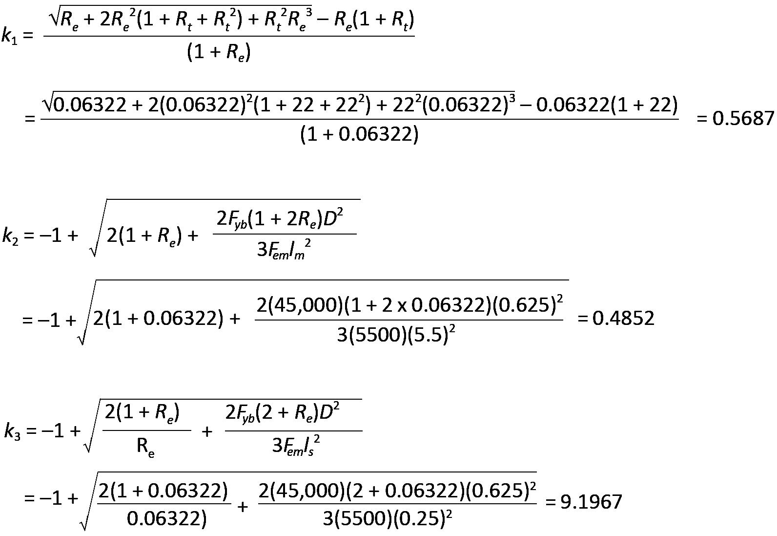
i. Compute Z for all applicable yield modes (four applicable modes for double shear):
For yield mode Im, Z = DlmFem /Rd = 0.625(5.5)(5500)/4 = 4726.6 lb.
For yield mode Is, Z = 2DlsFes /Rd = 2(0.625)(0.25)(87,000)/4 = 6796.9 lb for double shear.
Yield mode II does not apply to double shear connections.
Yield mode IIIm does not apply to double shear connections.
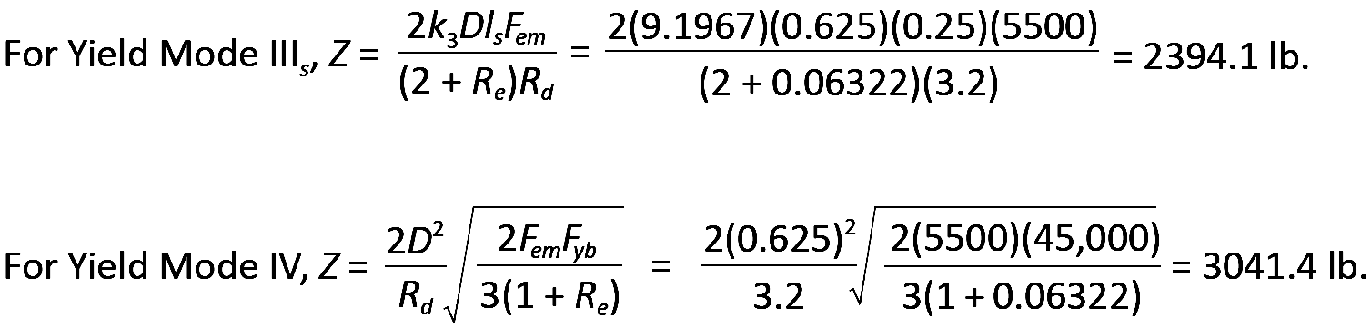
The smallest of the various yield mode values is then selected: Z = 2394.1 lb based on yield mode IIIs.
2. Penetration is only an issue with lag screws and nails, since bolts must always fully penetrate the members being connected. Therefore, no reduction of the lateral design value is necessary, and it remains equal to Z = 2394.1 lb.
3. Adjustments are as follows (same as for Example 3.12):
CD for typical values of live and dead load is 1.0 (Appendix Table A-3.20);
CM for members fabricated and used "dry" is 1.0 (Appendix Table A-3.21);
CΔ is found by testing four separate criteria (Appendix Table A-3.23): spacing between fasteners in a row; spacing between rows of fasteners; end distance; and edge distance. It is sometimes useful to sketch the members separately, showing dimensions for the relevant geometry factor parameters (Figure 3.48). Only the wood main member is considered here; the tension capacity and bolt spacing in the steel plate must be considered separately (see Chapter 4 for discussion of tension and bolt spacing in steel):
In the calculations that follow, D is the fastener diameter of 5/8 in. = 0.625 in.
Spacing criteria: Adjustment criteria for spacing appear in Appendix Table A-3.23, parts A and B. For spacing between fasteners in a row, where the loading direction is parallel to grain, the minimum spacing for full value is 4D = 4 × 0.625 = 2.5 in. Since the actual spacing is 2.5 in., the full value applies, and CΔ = 1.0. For spacing between rows of fasteners, again with the loading direction parallel to grain, the minimum required spacing is 1.5D = 1.5 × 0.625 = 0.9375 in. Since the actual spacing (between rows) of 2.5 in. exceeds this value, and is no greater than 5 in. (the maximum distance allowed between the outer rows of fasteners), the geometry factor is CΔ = 1.0.
End distance: Adjustment criteria for end distance appear in Appendix Table A-3.23, part C. For the main member, the loading direction is parallel to grain. Where the fasteners are bearing towards the member end (in "tension") and for "softwood," the minimum end distance for full value (i.e., for CΔ = 1.0) is 7D = 7 × 0.625 = 4.375 in. The actual end distance of 5 in. is greater than this, so the geometry factor, CΔ = 1.0.
Edge distance: Adjustment criteria for edge distance appear in Appendix Table A-3.23, part D. For the main member, the loading direction is parallel to grain, so the minimum edge distance is determined from the so-called slenderness ratio of the fastener, l/D. The fastener length, l, within the main member is 5-1/2 in., so l/D = 5.5/0.625 = 8.8. Since this value is greater than 6, the minimum edge distance is either 1.5D = 1.5 × 0.625 = 0.9375 in., or one half of the spacing between rows = 0.5 × 2.5 = 1.25 in., whichever is greater: the minimum edge distance is therefore 1.25 in., which the actual edge distance of 1.5 in. exceeds. The geometry factor therefore is CΔ = 1.0.
The geometry factor for the entire connection is found by using the smallest of the geometry factors found for any of the four conditions tested above (end, edge, and the two spacing conditions where applicable): therefore, we use CΔ = 1.0.
The adjusted lateral design value for a single bolt in the connection is found by multiplying the lateral design value from step 2 by the various adjustment factors determined in step 3: CD, CM, and CΔ: Z' = Z(CD)(CM)(CΔ) = 2394.1(1.0)(1.0)(1.0) = 2394.1 lb.
4. The group action factor, Cg, can be found based on the method described in Note 3 of Appendix Table A-3.22:
D = 0.625 in.
γ = 270,000(D1.5) = 270,000(0.6251.5) = 133,409.
s = 2.5 in.
Em = 1,600,000 psi (see Appendix Table A-3.9).
Es = 29,000,000 psi (see Chapter 4 for the modulus of elasticity of steel).
Am = 30.25 in2; As = 2(0.25 × 5.5) = 2.75 in2 (Appendix Table A-3.12).
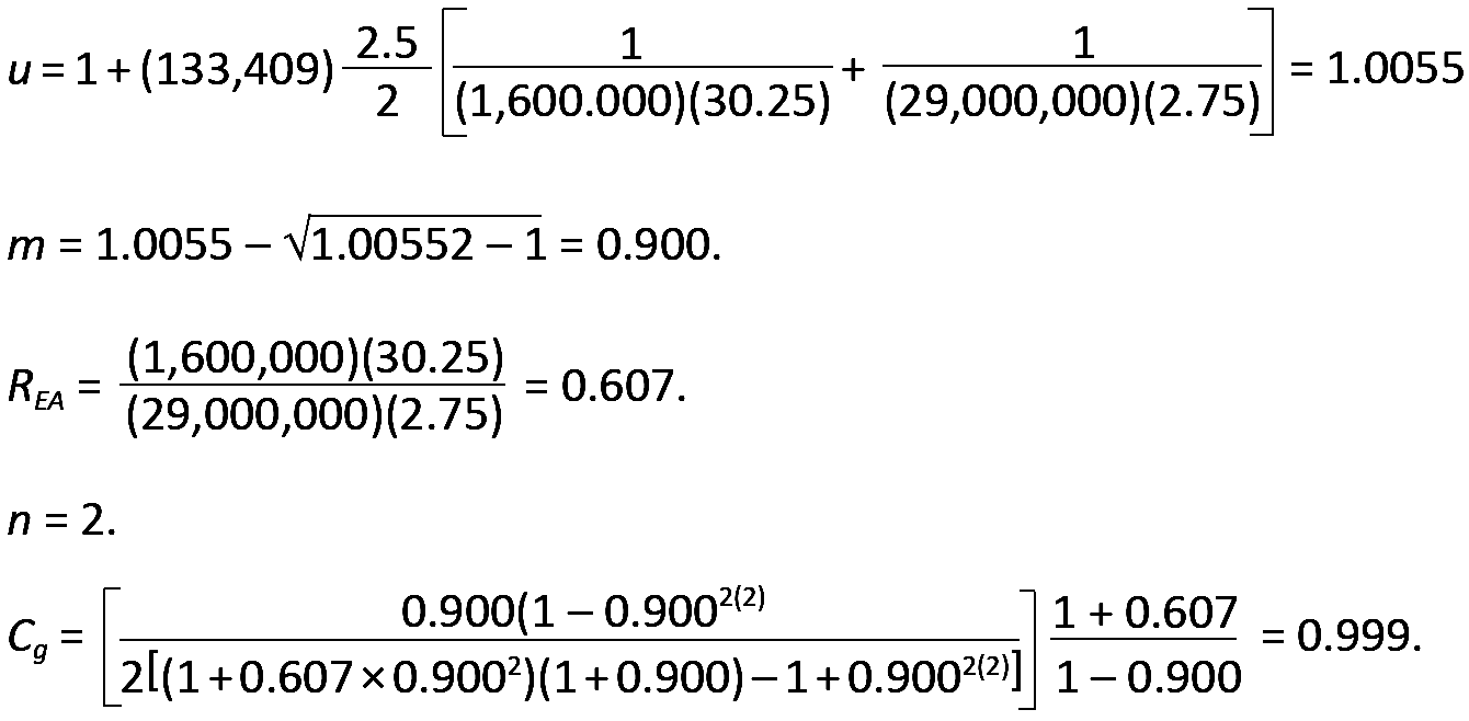
Adjusting for group action and multiplying the single-fastener value for Z' found in step 3 by the number of fasteners in the connection, we get a total adjusted connection capacity equal to 2394.1(0.999)(4) = 9567 lb.
5. We are not considering the design of the structural elements themselves in this example. Tension, row and group tear-out are considered in Example 3.1.
6. Conclusion: The total capacity of the connection (consisting of a six 1/2 in. diameter bolts) is 9567 lb.
Where a fastener is itself stressed in tension, it is considered to be loaded in "withdrawal," as a failure of the connection would cause it to "withdraw" — pull out — from the member into which it was inserted. For lag screws and nails, selected withdrawal design values, designated W to distinguish them from lateral design values, Z, are tabulated in Appendix Tables A-3.32 and A-3.33. These tabular values increase with higher wood specific gravity, G, and larger shaft diameter, D, and are based on the following empirical equations: for lag screws, W = 1800G3/2D3/4; for nails, W = 1380G5/2D. In these equations, W is the withdrawal design value per inch of penetration (lb); G is the specific gravity of the wood; and D is the fastener diameter (in.). While it is permitted to use nails in withdrawal, it is advisable to alter the connection geometry, if possible, so that such unthreaded fasteners are stressed in shear, rather than in tension. Unlike the penetration length of lag screws stressed in shear (laterally), the penetration of lag screws in withdrawal only includes that portion of the shank length that is both embedded in the main member, and threaded (excluding the tapered tip).
Lag screw withdrawal values must be reduced by 75% when the lag screws are inserted into the end grain of a wood member; nails are not permitted to be loaded in withdrawal from the end grain of wood members. Aside from computing the capacity of a connection based on computed withdrawal values, W, the tensile strength of lag screws loaded in withdrawal must also be checked, and, where the head (or washer) of the lag screw is in contact with a wood member, the bearing stress of the washer on this member must also be checked. Finally, the adjusted withdrawal capacity per inch of penetration, W', is computed by multiplying W by the appropriate adjustment factors: where in-service temperatures are no more than 100°F, only duration of load and wet service factors apply to fasteners in withdrawal (see Appendix Tables A-3.20 and A-3.21).
For bolted connections, "withdrawal" is not possible; instead, where bolts are placed in tension, the tensile strength of the bolt itself, as well as the bearing of the bolt (or washer) on the surface of the wood member, must be checked.
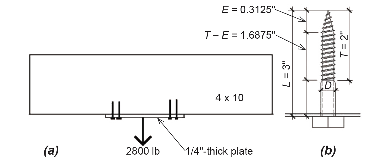
Problem definition. Determine the number of 3-in.-long, 1/2-in.-diameter, lag screws needed to connect a 1/4 in. steel plate holding a 2800 lb load to a 4 × 10 wood beam, as shown in Figure 3.49. The wood used is Spruce-Pine-Fir No.1/No.2, the loads are dead and live only (so that CD = 1.0), and the wood is fabricated and used dry. Assume that the steel plate capacity is adequate.
Solution overview. Find the capacity of a single lag screw in withdrawal; divide the total load by this value to determine the required number of lag screws.
Problem solution
1. From Appendix Table A-3.32, the withdrawal design value, W, per inch of penetration, is 291 lb, for a 3-in.-long, 1/2-in.-diameter lag screw. The adjusted value, W' = W(CD)(CM) = 291(1.0)(1.0) = 291 lb.
2. From Appendix Table A-3.17, it can be seen that the actual penetration into the main member (i.e., the length of the threaded portion of the lag screw that engages the main member, not including the tapered tip, or T – E) = 1.6875 in. Therefore, each lag screw resists (291)(1.6875) = 491 lb in withdrawal.
3. Since the total load to be resisted is 2800 lb, the required number of lag screws = 2800/491 = 5.7. Round up and use six 3-in.-long, 1/2-in.-diameter, lag screws.
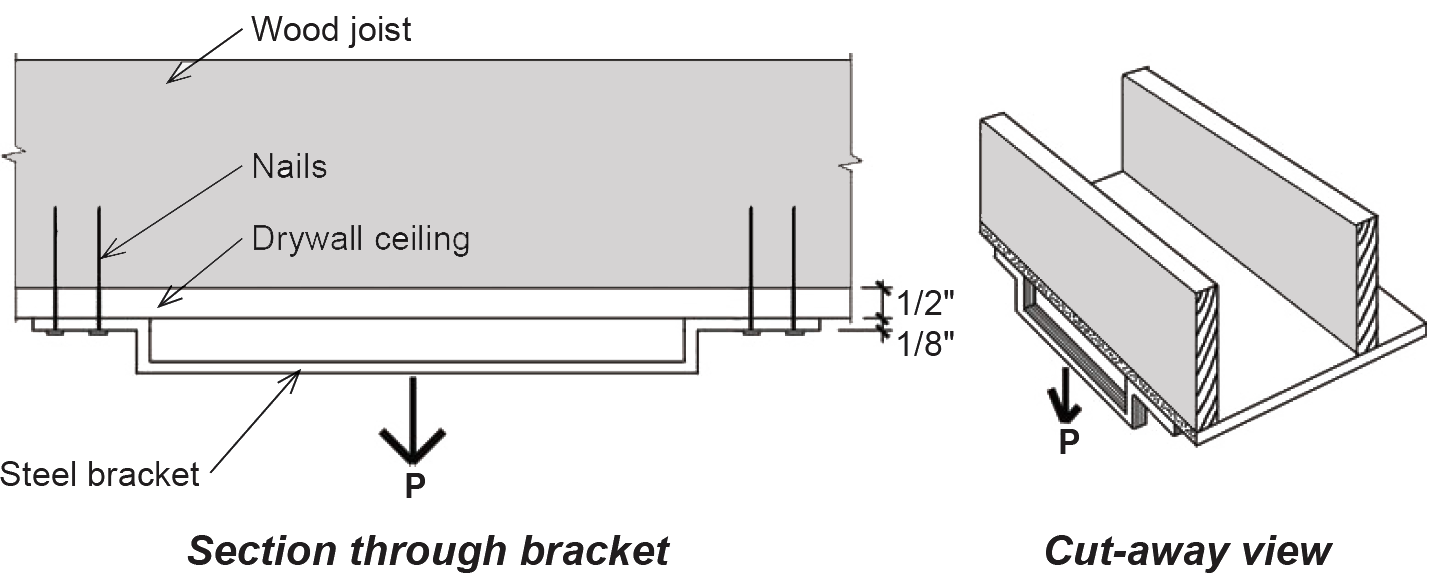
Problem definition. A steel bracket designed to hold heavy items is fastened to the floor joist above it using four 16d common nails, as shown in Figure 3.50. These nails must go through a 1/2 in. drywall ceiling, as well as the 1/8 in.-thick steel bracket itself, before reaching the wood joist, fabricated from Douglas Fir-Larch. How much load can the bracket carry, based on the capacity of the fasteners (and assuming that the strength of the bracket itself is adequate)?
Solution overview. Find the capacity of a single nail in withdrawal; multiply the single-nail capacity by the number of nails to find the capacity of the bracket.
Problem solution
1. From Appendix Table A-3.33, the withdrawal design value for a single 16d nail, W, per inch of penetration, is 40 lb. The adjusted value, W' = W(CD)(CM) = 40(0.9)(1.0) = 36 lb. The decision to use a value of CD = 0.9 is based on an evaluation of the loads, which are essentially of a permanent nature (i.e., dead loads).
2. The actual penetration into the main member is the total nail length minus the drywall and steel thickness; from Appendix Table A-3.18, we see that p = 3.5 – (1/2 + 1/8) = 2.875 in. Therefore, each nail resists (36)(2.875) = 103.5 lb in withdrawal.
3. Since there are four nails, the total capacity of the rack, P = 4(103.5) = 414 lb. However, it would be wiser to use a threaded connector (such as a screw or lag screw) instead of a nail in this situation.
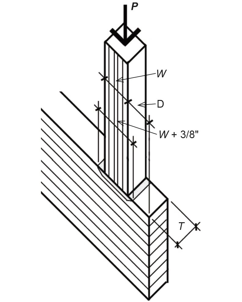
Where a wooden column or beam bears on another structural element, a compressive stress acts on the bearing surfaces. The use of the plural ("surfaces") indicates that bearing always acts in two directions, so that, for example, a joist bearing on a plate implies that the plate is also bearing on the joist. In theory, the bearing stress is the same on both surfaces; in practice, the effective bearing area in some cases may be increased by adding 3/8 in. in the direction of the bearing length — measured in the direction parallel to the grain of the wood — to account for the ability of the wood grain to distribute the load across a larger area. For the beam and post shown in Figure 3.51, the bearing stress of the post on the beam, or the beam on the post, is equal to the load, P, divided by the bearing area, W × T. Since wood is weaker when stressed perpendicular to its grain, the critical bearing stress will almost always occur acting downward on the surface of the beam, rather than upward on the post. If the distance, D, measured from the edge of the post to the end of the beam, is greater than three inches, and the bearing length, W, of the post is less than six inches, we can reduce the effective bearing stress of the post on the beam by dividing the load, P, by the larger effective bearing area, T × (W + 3/8 in.). This stress is then compared to the adjusted allowable compressive stress (perpendicular to grain). For joists and other beams, the allowable stress is in compression, perpendicular to the grain of the wood, whereas when considering the bearing stress on columns, the allowable stress value is taken for compression parallel to grain (but without including the adjustment factor for stability, since buckling is not relevant at the surface where bearing stresses are being measured).
For compressive stresses parallel to grain, a steel plate must be used at the point of bearing to distribute such stresses more evenly across the surfaces in contact, but only in cases when these stresses exceed 75% of Fc*. See Appendix Table A-3.4 for adjustments to allowable compressive stresses.
Problem definition. A 4 × 4 post bears at the midpoint of a 4 × 10 girder. The 5000 lb load transferred to the girder through the post consists of live, dead, and wind loads. Check whether the bearing capacity is adequate, assuming that both members are Hem-Fir No.2.
Solution overview. Find the effective bearing area of the post on the girder; find the actual "effective" bearing stress on the girder; compare this stress to the allowable compressive stress perpendicular to grain.
Problem solution
1. Because the post has a bearing length less than six inches, and is more than three inches from the end of the girder, we can use an effective bearing length 3/8 in. greater than its actual bearing length of 3.5 in. (see Appendix Table A-3.12 for cross-sectional dimensions). The effective bearing area is therefore = T × (W + 3/8) = 3.5(3.5 + 0.375) = 13.56 in2. The actual bearing stress on surface of the girder = 5000/13.56 = 369 psi.
2. This value is compared with the adjusted allowable bearing stress, F'c-per. From Appendix Table A-3.3, the design value for compression perpendicular to grain for the Hem-Fir girder is Fc-per = 405 psi.
3. Assuming that the members are used indoors, the only potentially relevant adjustment factor, for wet service, doesn't apply. CM is taken as 0.67 only when the moisture content is greater than 19% for long periods of time — i.e., when used outdoors — but can be taken as 1.0 when used indoors; the size and duration of load factors do not apply to compression perpendicular to grain. Therefore, F'c-per = 405(1.0) = 405 psi, which is greater than the actual effective bearing stress. The connection is satisfactory with respect to bearing.
4. The 4 × 4 post need not be directly checked for bearing stress (since its allowable stress in compression parallel to grain will be greater than the girder's allowable stress perpendicular to grain). However, we check to see whether the actual stress on the post exceeds 75% of Fc*, the allowable compressive stress parallel to grain with all adjustments except for the column stability factor; if it does, a steel bearing plate should be specified. The actual stress is the load divided by the post area, or 5000/(3.5 × 3.5) = 408 psi, where the cross-sectional dimensions can be found in Appendix Table A-3.12. From Appendix Tables A-3.3 and A-3.4, the adjusted allowable stress (without Cp) multiplied by 75% is (0.75)1300(1.15)(1.0) = 1121 psi (the size factor, CF = 1.15, for the 4 × 4 post). Since this value is greater than the actual stress, no bearing plates are required between the post and girder.
In the design of such a connection, it must not be assumed that gravity will hold the post firmly against the girder under all conditions; the two members must also be mechanically connected to guard against unintended movement.
© 2020 Jonathan Ochshorn; all rights reserved. This section first posted November 15, 2020; last updated November 15, 2020.