
Contents | 1. Introduction to structural design | 2. Loads | 3. Wood |
Introduction to steel | Material properties | Sectional properties | Design approaches |
Steel-framed structures often consist of columns, girders, beams, and corrugated steel decks (with concrete fill when used for floors and for some roofs), stabilized with some sort of lateral-force-resisting system. In fact, it is common for all major steel elements in a building structure to consist of a single cross-sectional type: the wide-flange (W) shape. These shapes are remarkably versatile and efficient, especially for bending (beams), but also for columns. Such "open" cross sections facilitate making connections with clip angles, bolts, and welds. "Closed" sections, such as round or rectangular hollow structural sections (HSS), cannot be as easily bolted together, since their insides are inaccessible — how would you tighten the nut on a bolt, or even get the nut inside such a cross section? On the other hand, it is fairly easy to overcome this problem by welding small plates to the closed sections in the steel fabrication shop; these plates, being open, can be easily bolted to adjacent elements. Alternatively, but with somewhat more difficulty and expense, closed structural elements can be directly welded to each other in the field, as can open cross sections.
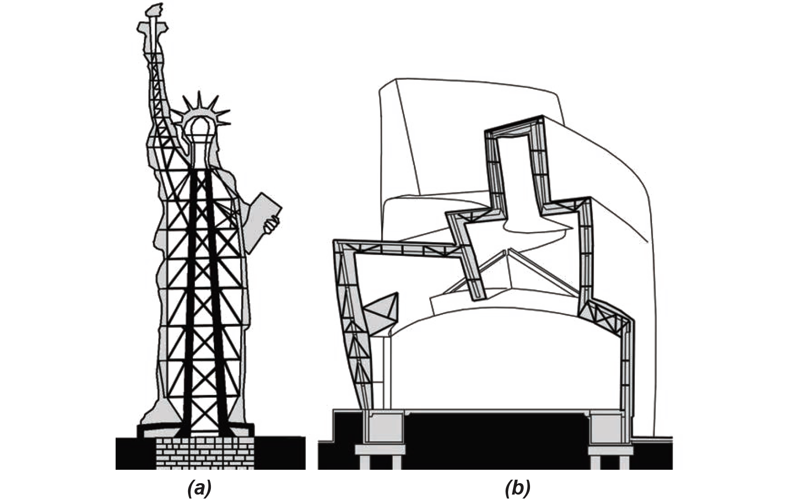
There really are no limits to the ways in which steel can be configured as structure; numerous examples can be found that illustrate creative and unusual applications utilizing assemblages of cables, rods, and plates, along with standard rolled sections and even one-of-a-kind steel castings (while not particularly common, steel can be cast as well as hot-rolled). Sections can be bent and curved; plates can be cut; and all sorts of composite elements can be configured by welding or bolting the various pieces together. Yet, in spite of this potential, most steel-framed buildings are far more conventional in their choices of elements and connections. Even buildings whose "architectural" qualities are highly idiosyncratic may hide rather conventional skeletal structures beneath their expressive outer forms; the Statue of Liberty, while not exactly a "building," nevertheless illustrates this strategy (Figure 4.5a). On the other hand, as demonstrated in the Guggenheim Museum Bilbao, it is possible to twist and distort the structure itself so that it directly follows the contours of the architectural form (Figure 4.5b).
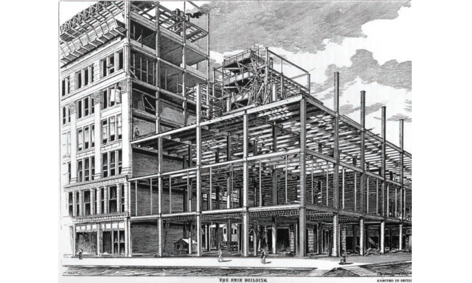
Most steel-framed buildings are neither defined by complex doubly curved forms nor supported by inventive or unusual structural systems. Instead, they most often have "skeletal" steel frames consisting of wide-flange columns, girders, and beams. This hierarchical pattern of steel structural elements really hasn't changed much since the late nineteenth century (Figure 4.6), except that spans have increased as steel as gotten stronger, floor systems no longer rely on short masonry arches spanning between closely-spaced beams to provide fire protection, and riveted connections have been superseded by bolts and welds. Columns are still typically aligned on an orthogonal grid with girders spanning between columns in one direction only and beams spanning between girders (but with some beams aligning with — and therefore supported by — the columns) approximately 10 feet apart, more or less. This spacing between beams, which is actually quite variable, corresponds to the allowable span of corrugated steel decks (often designed to act compositely with concrete fill, in which case they really behave more like reinforced concrete slabs than steel decks).
Span tables are provided by steel deck manufacturers and are easily found online. Variables in these span tables include the gauge (thickness) of the sheet steel used to fabricate the corrugated deck, the centerline spacing of beams between which the deck is spanning, the thickness of the deck (or the deck "type"), the total thickness of the composite deck (including the concrete fill), and the weight of the concrete (normalweight concrete is stronger than lightweight concrete). Concrete fill is always used in corrugated deck floor systems, at a minimum to provide a horizontal surface to support human occupation directly, or to support a so-called finish floor — carpet, tile, wood, etc. — but often also to provide the compressive resistance which, together with the steel deck acting in tension compositely with the concrete, comprises the structural spanning element between beams. Such fill is often omitted in roof systems, since loads acting on the roof may be smaller, and rigid insulation, placed directly over the corrugated steel deck, can be used as the necessary horizontal substrate for various single-ply roofing systems.
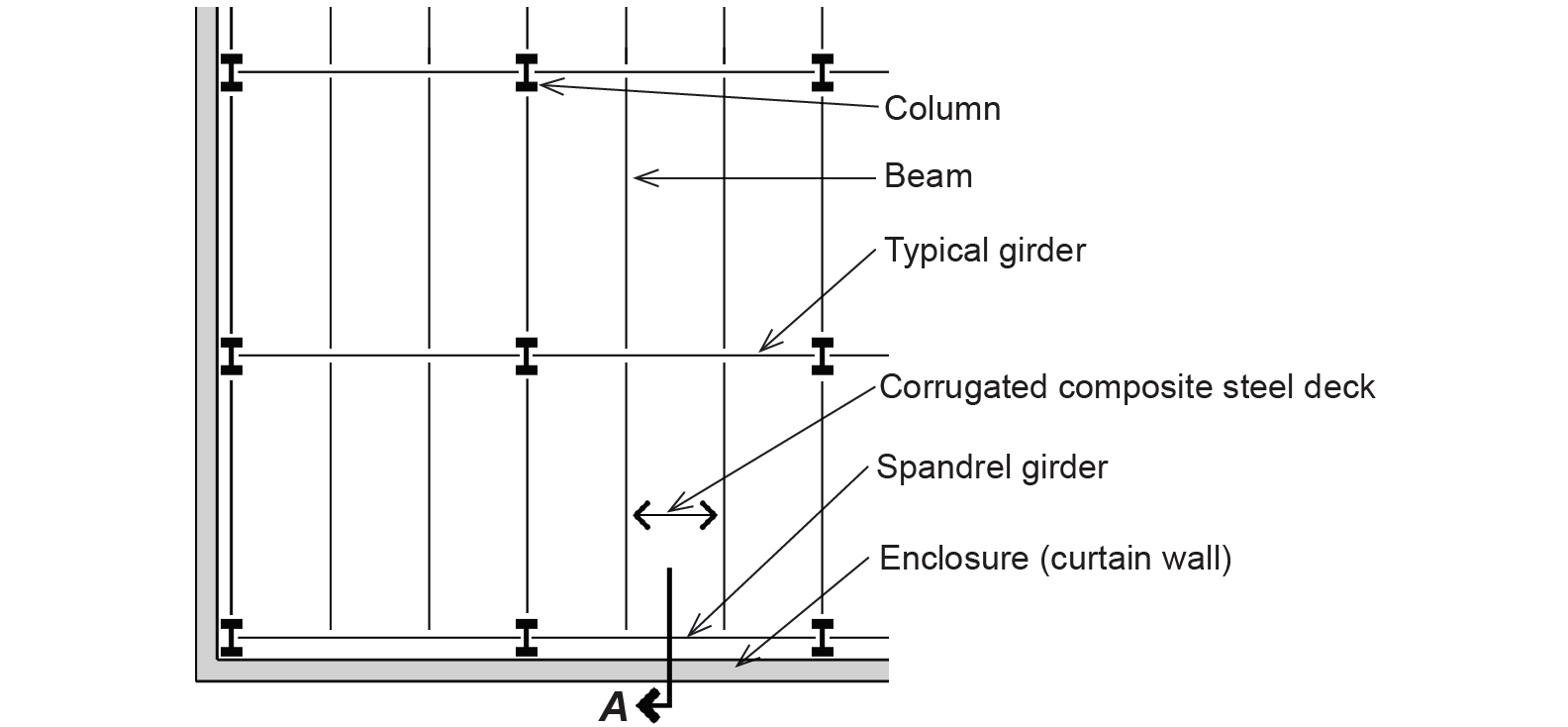
In plan, the typical pattern of columns, girders, and beams appears as shown in Figure 4.7, with the distance between columns often in the range of 30–40 ft, or even more (the spacing of such columns in late 19th-century or early 20th-century buildings is typically closer to 15 ft).
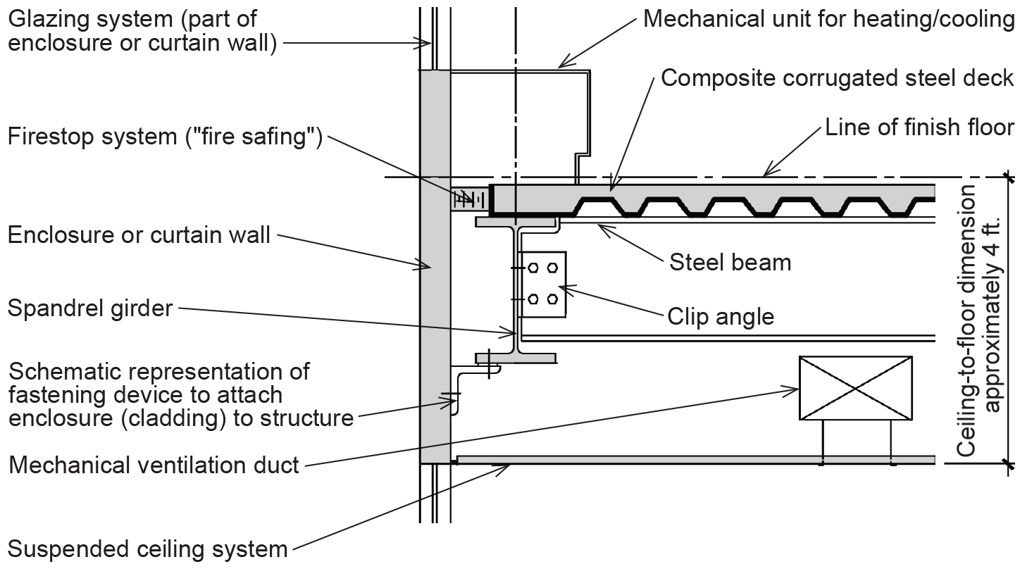
At the edge, or spandrel, girder, some sort of curtain wall system is "hung" from the steel frame, and various mechanical/electrical/plumbing systems are inserted between the bottom of the floor structure and the top of a suspended ceiling (unless some or all of these systems are placed above the floor structure, under a raised access floor system). The connection of enclosure system to structure, along with other elements typically found in this type of steel-framed construction, is represented schematically in Figure 4.8. In order that the top flanges of the beams and girders align (so that the corrugated steel deck can be placed on a consistently level grid of structural elements), the ends of beams framing into girders are coped, or cut. In this way, as shown in Figure 4.8, the beam's web can be fastened to the girder's web without having the beam's top flange collide with the top flange of the girder.
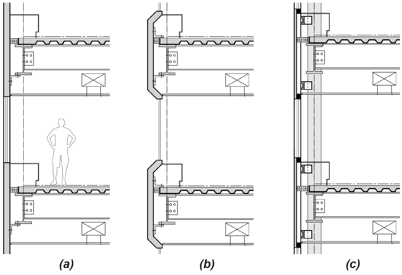
Other strategies for attaching enclosure systems to steel framing systems are represented in Figure 4.9. From left to right, the strategies show (a) vertical supports for the enclosure system spanning from floor to floor, (b) enclosure system elements supported entirely from a single floor, and (c) truss-supported enclosure systems spanning horizontally from column to column — the black squares in this last image represent the top and bottom chords of the trusses. Of the three systems, the first is commonly associated with aluminum and glass curtain walls but can also be adapted to various other systems (e.g., metal panels, precast panels, EIFS, stone veneer, brick veneer with steel stud support, etc.); the second can be used with precast concrete or other cladding panels where a continuous band of horizontal glazing is desired, and the third — less commonly encountered than the other strategies — can be used where off-site fabrication of large enclosure panels is desired.
Columns in multi-story steel-framed buildings must be spliced together from smaller lengths. In general, the largest lengths compatible with transport and erection constraints are used in order to minimize the work needed on-site to make such connections. This typically results in two- or three-story column lengths that are connected above the finish floor levels, as shown in Figure 4.10a. Small inefficiencies come about from this strategy, since the upper part of a typical two- or three-story section is stronger than it would otherwise need to be (its strength being governed by the heavier loads supported on the lower part of the section), but such inefficiencies are justified by savings in fabrication and erection costs. Steel cap and base plates may or may not be used where steel column sections are joined together; the simplest connections omit such plates in favor of "filler" or "packing" plates that account for misalignment of flange and web surfaces (where adjacent columns are not the same size) so that splice plates can tie the separate elements together (Figure 4.10b).
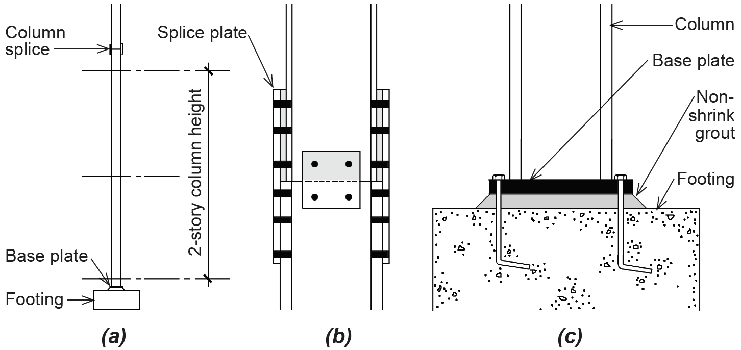
Where columns meet the foundation, and therefore must be connected to the building's reinforced concrete substructure, base plates are always used. These plates, which are typically shop-welded or bolted to the bottom of the lowest steel columns, do not actually touch the top surface of the concrete substructure, but are designed to be "suspended" about an inch or less above the top surface of the concrete. Such tolerances are always required, since as-built conditions of both steel and concrete systems cannot be assumed to have the precision of, for example, factory-made components like windows or doors. The vertical alignment of steel columns is then carefully adjusted in the field, using shims or leveling bolts under the base plate, and the space between base plate and footing is filled with non-shrink grout so that compressive loads may be transferred from the column to the foundation (Figure 4.10c). Threaded rods, already positioned in the concrete substructure so that they align with bolt holes in the column base plate, are designed to prevent both lateral and vertical movement of the column when nuts are screwed onto the rods and tightened against the top of the base plates.
© 2020 Jonathan Ochshorn; all rights reserved. This section first posted November 15, 2020; last updated November 15, 2020.