
Contents | 1. Introduction to structural design | 2. Loads | 3. Wood |
Introduction to steel | Material properties | Sectional properties | Design approaches | Construction systems | Tension elements | Columns |
The design of steel wide-flange beams using the "allowable strength design" method is quite similar to the procedures used to design timber beams (see Chapter 3). Cross sections are selected based on their strength in bending, and then checked for shear and deflection.
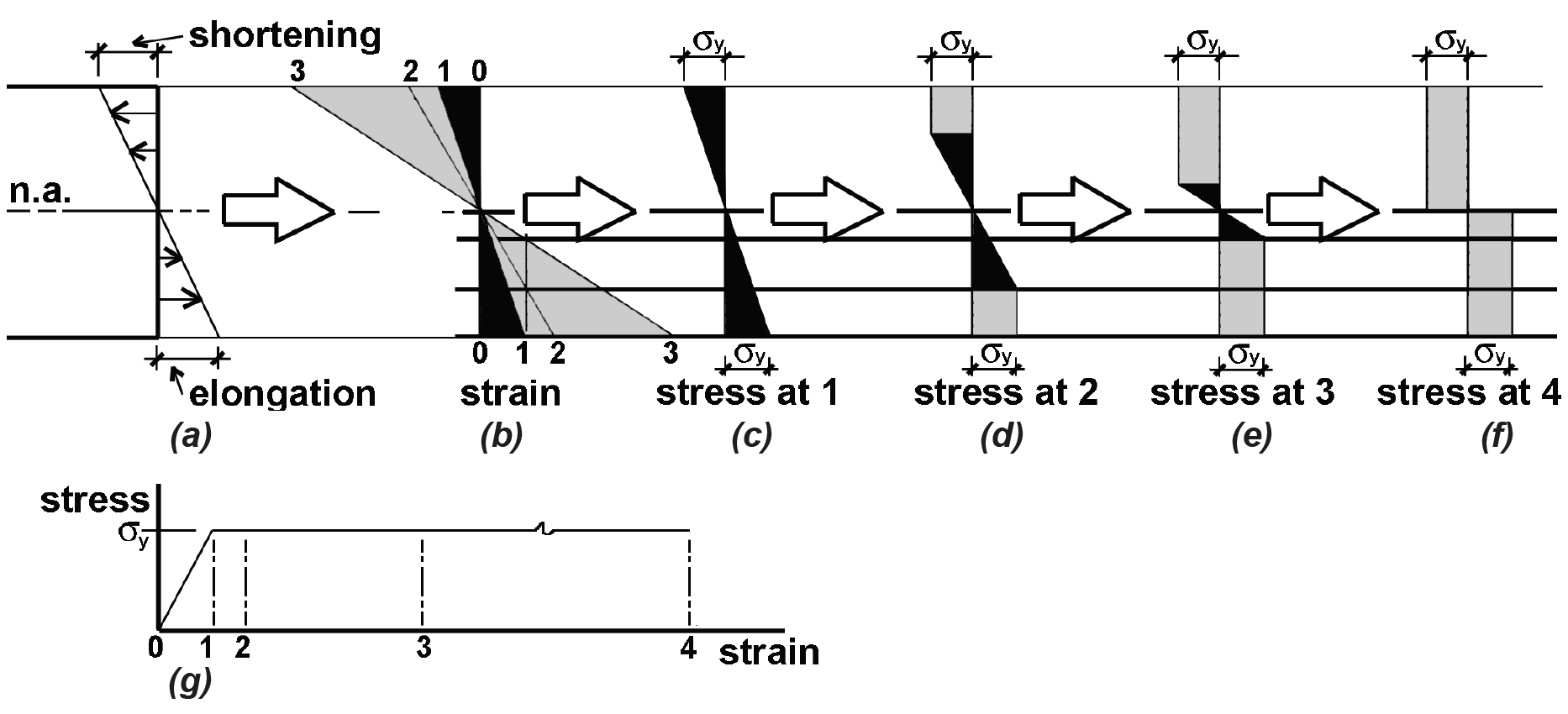
Unlike wood beams, however, steel beams are designed based on their "available" strength, rather than on the more convention notion of an "allowable" stress. Whereas the strength of a wood beam corresponds to its outer fibers reaching a failure stress, steel beams do not fail when their outer fibers first begin to yield at the stress, Fy. A steel cross section is able to carry increased loads beyond the so-called elastic moment, shown in Figure 4.21a, up until the entire cross section has yielded, as shown in Figure 4.21b. The plastic section modulus corresponds to this so-called plastic moment, reached when the strain at a cross section is of sufficient magnitude so that virtually the entire section has yielded.
Previously, steel used an "allowable stress" method based on a limit state corresponding to the elastic moment; and if the plastic moment were always stronger than the elastic moment to the same extent for all cross sections, one could simply adjust the factor of safety for allowable strength (plastic moment) design so that the method corresponded precisely to allowable stress (elastic moment) design. However, it can be shown that the extra margin of safety gained by moving beyond the elastic, to the plastic moment (i.e., from the condition of Figure 4.21a to Figure 4.21b), is not the same for all cross sections, so that allowable stress design for steel does not provide a consistent margin of safety against the limit state of complete yielding.
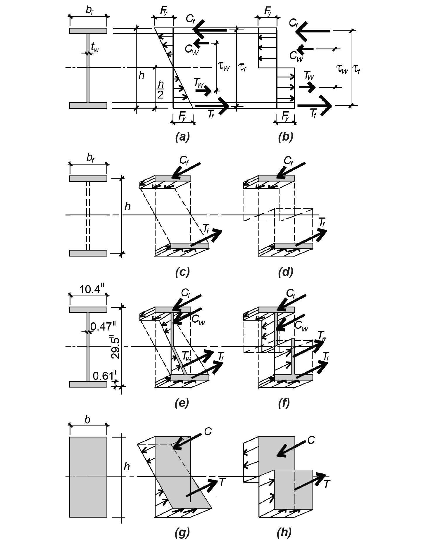
For wide-flange (![]() -shaped) sections, the extremes can be represented by a hypothetical section with no web (i.e., consisting entirely of flanges of infinite density, or no thickness, as shown in Figures 4.21c and 4.21d); and, at the other extreme, a section whose flanges merge together at the neutral axis (i.e., a rectangular section, as shown in Figures 4.21g and 4.21h). In the first case, it is clear that the elastic moment and plastic moment coincide, and the so-called "shape factor" defining the ratio of plastic to elastic section modulus, Zx/Sx, equals 1.0. In the second case, the elastic section modulus can be computed by examining the rotational equilibrium of the force resultants shown in Figure 4.21g. Since the moment arm between them equals (2/3)h, and the resultant force, C, equals (1/2)(h/2)(b)(Fy), the moment, M, equals (2/3)(h)(1/2)(h/2)(b)(Fy ) and, solving for the section modulus, Sx = M/Fy, we get Sx = bh2/6. Performing the same equilibrium calculation on Figure 4.21h (with a moment arm equal to h/2), and solving for the plastic section modulus, Zx = M/Fy , we get Zx = bh2/4. The shape factor in this case is Zx/Sx = 1.5.
-shaped) sections, the extremes can be represented by a hypothetical section with no web (i.e., consisting entirely of flanges of infinite density, or no thickness, as shown in Figures 4.21c and 4.21d); and, at the other extreme, a section whose flanges merge together at the neutral axis (i.e., a rectangular section, as shown in Figures 4.21g and 4.21h). In the first case, it is clear that the elastic moment and plastic moment coincide, and the so-called "shape factor" defining the ratio of plastic to elastic section modulus, Zx/Sx, equals 1.0. In the second case, the elastic section modulus can be computed by examining the rotational equilibrium of the force resultants shown in Figure 4.21g. Since the moment arm between them equals (2/3)h, and the resultant force, C, equals (1/2)(h/2)(b)(Fy), the moment, M, equals (2/3)(h)(1/2)(h/2)(b)(Fy ) and, solving for the section modulus, Sx = M/Fy, we get Sx = bh2/6. Performing the same equilibrium calculation on Figure 4.21h (with a moment arm equal to h/2), and solving for the plastic section modulus, Zx = M/Fy , we get Zx = bh2/4. The shape factor in this case is Zx/Sx = 1.5.
Clearly, all ![]() -shaped sections must have a shape factor between these two extremes, i.e., between 1.0 and 1.5. The shape factor for a typical W-shape (W30 × 90), shown in Figures 4.21e and 4.21f, can be determined in the same manner, abstracting from the complexities of the actual shape by considering only perfectly rectangular flange and web areas. Using the dimensions shown, and performing the same equilibrium calculations as in the cases above, we get Sx = 240 in3 and Zx = 277 in3, so the shape factor, Zx/Sx = 277/240 = 1.15. The actual values for elastic and plastic section modulus are found in Appendix Table A-4.3, and it can be seen that the approximate calculations are both conservative and reasonably accurate: the correct values are actually Sx = 245 in3 and Zx = 283 in3, so the real shape factor, Zx/Sx = 283/245 = 1.16.
-shaped sections must have a shape factor between these two extremes, i.e., between 1.0 and 1.5. The shape factor for a typical W-shape (W30 × 90), shown in Figures 4.21e and 4.21f, can be determined in the same manner, abstracting from the complexities of the actual shape by considering only perfectly rectangular flange and web areas. Using the dimensions shown, and performing the same equilibrium calculations as in the cases above, we get Sx = 240 in3 and Zx = 277 in3, so the shape factor, Zx/Sx = 277/240 = 1.15. The actual values for elastic and plastic section modulus are found in Appendix Table A-4.3, and it can be seen that the approximate calculations are both conservative and reasonably accurate: the correct values are actually Sx = 245 in3 and Zx = 283 in3, so the real shape factor, Zx/Sx = 283/245 = 1.16.
The equation for plastic section modulus, Zx = M/Fy, presumes that the cross section is able to reach a state of complete yielding before one of two types of buckling occurs: either lateral-torsional buckling within any unbraced segment along the length of the span or local flange or web buckling. Therefore, to use this equation in design, based on the maximum moment encountered, the beam must be protected from both of these buckling modes, in the first case by limiting the effective length and, in the second case, by regulating the proportions of the beam flange and web (i.e., using a so-called compact section). Then, rewriting this equation in the form most useful for steel design, we get:
where Mmax = the maximum bending moment (in-kips), Fy is the yield stress of the steel (ksi), and Ω is a safety factor equal to 1.67 for bending. The units of the required plastic section modulus are in3.
We found earlier that the shape factor for a W30 × 90 section equals 1.16. By looking at the ratio of plastic to elastic section modulus for all wide-flange shapes, it can be seen that these shape factors fall between 1.098 (for a W14 × 90), and 1.297 (for a W14 × 730). One could therefore conservatively create a safety factor for elastic allowable stress design by assuming a shape factor of 1.10, and by multiplying this value by the safety factor for allowable strength design, 1/Ω = 1/1.67 = 0.60 (inverted to be consistent with the conventions for allowable stress safety factors). Equation 4.12 would then become Sreq = Mmax /(1.1 × 0.6 × Fy ) = Mmax / (0.66Fy). This, in fact, is the design equation for what used to be called "allowable stress design" in steel. It may still be used, but will give slightly conservative values compared with the available stress method using the plastic section modulus, Zx. Choosing the lightest (i.e., most economical) laterally-braced, compact section is facilitated by the use of tables in which steel cross sections are ranked, first in terms of plastic section modulus, and then by least weight. Appendix Table A-4.15 is an example of such a list, in which only the lightest sections appear. Thus, a W30 × 191 (with a plastic section modulus of 675 in3) is not listed, since a lighter section, W40 × 167, has a higher plastic section modulus (693 in3).
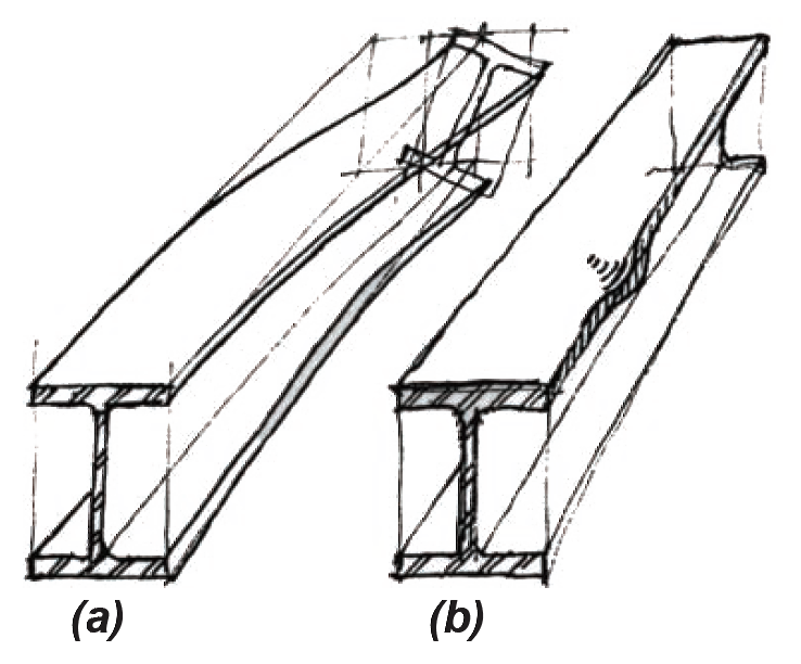
When the compression flange of a beam is not continuously braced, lateral-torsional buckling can reduce the available bending moment below the value of Mp/Ω assumed earlier for laterally braced beams. How much this stress is reduced depends on whether the beam buckles before or after the cross section begins to yield, and how bending stresses vary over the beam's effective length. Figure 4.22 shows several possible stress stages for a cross-sectional shape as the bending moment increases. At Figure 4.22c, the outer fibers begin to yield, and the elastic moment, My, is reached. At Figure 4.22d and Figure 4.22e, yielding progresses further into the cross section, as the moment increases. Finally, at Figure 4.22f, the entire cross section has yielded at the maximum plastic moment that the section can sustain.
Being able to resist the full plastic moment represents an extra margin of safety: if a beam can develop this plastic moment without buckling, the maximum available bending moment of Mp/Ω is used, as shown in Equation 4.12. In addition to lateral-torsional buckling (Figure 4.23a), various types of local flange and web buckling must also be prevented from occurring before the plastic moment is reached (Figure 4.23b). Local buckling is prevented by limiting the ratio of flange width to flange thickness, as well as web width to web thickness. Sections proportioned so that local buckling will not occur are called compact sections; these sections must be used to qualify for the full available moment of Mp/Ω. As it turns out, all but one of the wide-flange shapes listed in Appendix Table A-4.3 are compact sections when made from A36 steel (the exception being W6 × 15). For 50 ksi steel, all but ten (W6 × 8.5, W6 × 9, W6 × 15, W8 × 10, W8 × 31, W10 × 12, W12 × 65, W14 × 90, W14 × 99, and W21 × 48) are compact.
For sections that are compact and laterally braced, Equation 4.12 applies, and the full strength of the beam is utilized. However, as shown in Figure 4.24, this available strength must be reduced if either local flange buckling (where the section is not compact) or lateral-torsional buckling (where the section is not adequately braced) occurs before the plastic moment is reached.
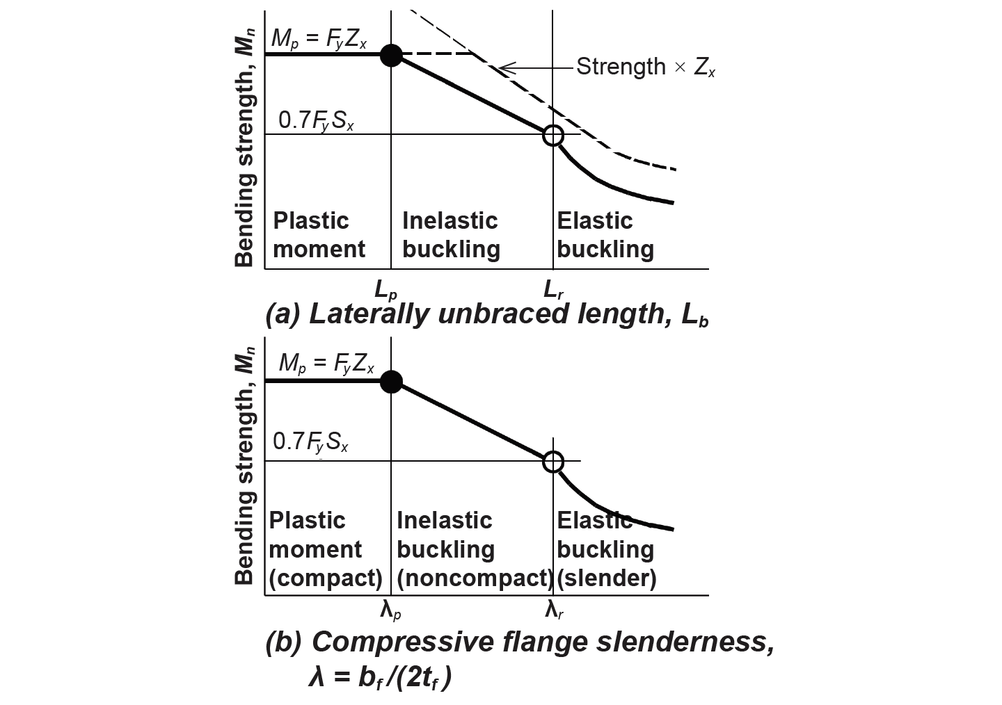
For beams with an unbraced length, Lb, that falls within the "middle zone" illustrated in Figure 4.24a (i.e., where the onset of buckling occurs before a full plastic moment, but after the elastic moment, is reached), the nominal bending strength is linearly reduced from the full plastic moment, Mp = FyZx, to 70% of the elastic moment, or 0.7FySx. The two boundaries (unbraced lengths) that bracket this condition of inelastic lateral-torsional buckling are called Lp and Lr. For an unbraced length, Lb, less than Lp, lateral-torsional buckling is not an issue, as the full plastic moment can be reached. For an unbraced length greater than Lr, the onset of lateral-torsional buckling is characterized entirely by elastic behavior, and the nominal bending strength must be reduced even further. These boundaries are defined as follows: Lp is set at 1.76ry![]() , where E is the modulus of elasticity (29,000 ksi for all steel), Fy is the yield stress (50 ksi for A992 steel, and 36 ksi for A36 steel), and ry is the minimum radius of gyration about the y-axis (see Appendix Table A-4.3 for wide-flange shapes). The other boundary, Lr, can be conservatively approximated as πrts
, where E is the modulus of elasticity (29,000 ksi for all steel), Fy is the yield stress (50 ksi for A992 steel, and 36 ksi for A36 steel), and ry is the minimum radius of gyration about the y-axis (see Appendix Table A-4.3 for wide-flange shapes). The other boundary, Lr, can be conservatively approximated as πrts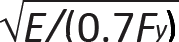 , where rts may itself be approximated as the radius of gyration for the compression flange and part of the web; i.e., rts = bf/
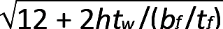 . In this equation, bf and tf are the flange width and thickness, respectively, and h is the length of the "straight" part of the web (i.e., the clear distance between flanges, minus the radii at the web-flange intersections).
However, all these equations are based on the assumption that the beam is subject to a uniform bending moment along its entire length; where the moment varies, as is almost always the case, this assumption is overly conservative, since lateral-torsional buckling is less likely to be triggered where bending stresses are not entirely at their maximum value along the whole length of an unbraced segment. For this reason, a coefficient, Cb, should be applied to the available strength of each unbraced segment of the beam, based on the distribution and magnitude of bending moments along that segment's length. This "lateral-torsional buckling modifier" is defined as follows for doubly-symmetric bending elements such as wide-flange beams:
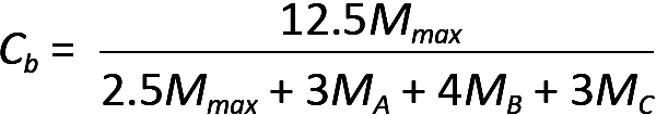
where Mmax is the greatest moment within the unbraced segment; and MA, MB, and MC are the bending moments at the quarter point, midpoint, and three-quarters point, respectively, along the segment. Where a segment is not braced at its endpoint (for example, where the end of a cantilevered beam is not braced), Cb should be taken as 1.0. Of course, Cb is not used where a beam is laterally braced and, in any case, can never increase the nominal bending strength beyond the plastic moment, Mp, as shown in Figure 4.24a.
Compact sections are proportioned so that neither the flange nor the web will buckle locally before
the onset of a plastic moment. Since all wide-flange webs meet the standards for compact sections,
only the flange slenderness, defined as λ = bf/(2tf ), is at issue (where bf and tf are the flange width
and thickness, respectively). In much the same way that boundaries are established for unbraced
length that define the reduction in the bending strength due to lateral-torsional buckling (Figure
4.24a), similar boundaries are established for flange slenderness, with similar consequences for
beam strength (Figure 4.24b). The limit for compact behavior — i.e., the maximum flange slenderness for which beams are still able to reach the plastic moment without local flange buckling — is
defined by λp = 0.38![]() . The other boundary (i.e., the maximum flange slenderness for which inelastic behavior characterizes the onset of local flange buckling) is defined by λr = 1.0
. The other boundary (i.e., the maximum flange slenderness for which inelastic behavior characterizes the onset of local flange buckling) is defined by λr = 1.0![]() . In these equations, E is the modulus of elasticity of steel (29,000 ksi) and Fy is the material's yield stress (50 ksi for A992 steel, and 36 ksi for A36 steel). As with reductions for lateral-torsional buckling, the nominal bending strength begins with the plastic moment, Mp = FyZx, for compact sections, and is linearly reduced to 70% of the elastic moment, or 0.7FySx, between λp and λr, with further reductions beyond λr.
. In these equations, E is the modulus of elasticity of steel (29,000 ksi) and Fy is the material's yield stress (50 ksi for A992 steel, and 36 ksi for A36 steel). As with reductions for lateral-torsional buckling, the nominal bending strength begins with the plastic moment, Mp = FyZx, for compact sections, and is linearly reduced to 70% of the elastic moment, or 0.7FySx, between λp and λr, with further reductions beyond λr.
Where a beam is both noncompact and laterally unbraced, both criteria illustrated in Figure 4.24 are tested, and the smaller capacity governs. For beams that are both compact and laterally braced, Appendix Table A-4.15 can be used to select the lightest W-shape for bending. For A992 wide-flange beams that are not adequately braced laterally (i.e, where Lb > Lp), Appendix Table A-4.16 can be used to select the lightest beam. Of course, by setting the unbraced length to zero, Appendix Table A-4.16 can be used for laterally-braced beams as well.
Once a selection is made based on bending stress, the section is then checked for shear and deflection. The nominal shear strength, Vn , equals 0.6FyAw, where Fy is the yield stress of the steel and Aw is the web area (equal to the beam depth times the web thickness, d × tw). For most cross sections, the safety factor can be taken as Ω = 1.5, so that the available strength is Vn/Ω = 0.6/Ω(FyAw) = 0.4FyAw. This can be converted into an "allowable stress" equation by defining the allowable shear stress, Fv = 0.4Fy, and solving for the required web area for a given shear force, V:
For a small group of wide-flange beams with slender webs, the safety factor for shear is increased from 1.5 to 1.67, and so the allowable shear stress becomes Fv = (0.6/1.67)Fy = 0.36Fy. These sections are listed in Appendix Table A-4.3 (see Note 3).
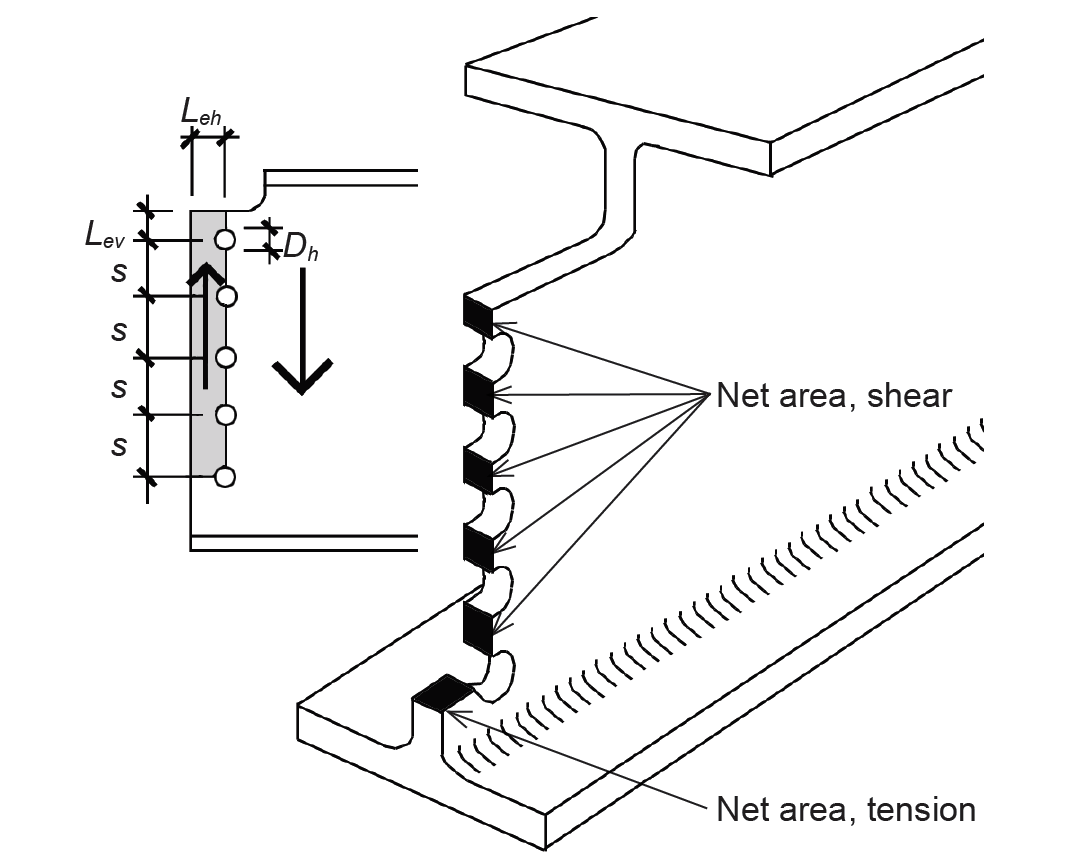
Where the top flange of a steel beam is coped (so that it may be fastened to the web of a girder while keeping the top surfaces of girder and beam flanges aligned), a mode of failure combining both shear and tension stresses in the beam web must be checked, with the shear and tension failure planes assumed to occur at the surface defined by the bolt centerline, as shown in Figure 4.25.
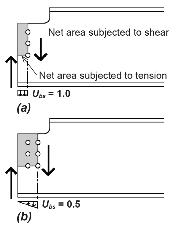
The nominal capacity of such a connection is found by adding the capacity of the net shear area subject to rupture (or the gross shear area subject to yielding) to the capacity of the net tension area subject to rupture. Where both net areas are subject to rupture, the capacity is defined as: Rn = 0.6FuAnv + UbsFuAnt. Where yielding governs the failure of the shear area, the capacity is defined as: Rn = 0.6Fy Agv + UbsFuAnt. The smaller of these two values determines the capacity of the connection for resisting block shear. In these equations, Fu is the minimum tension strength of the material (equal to 58 ksi for A36 steel, and 65 ksi for A992 steel); Anv and Ant are the net areas for shear and tension, respectively; Agv is the gross shear area; and Ubs equals 1.0 for conditions that correspond to uniform tension stress, as in the coped beam with a single line of bolts shown in Figure 4.25a, while Ubs equals 0.5 for conditions that lead to a triangular (nonuniform) tension stress, as in the coped beam with a two lines of bolts shown in Figure 4.25b. The available strength is then found by dividing the nominal capacity by the safety factor, Ω = 2.00.
It is also possible that a mode of shear failure alone, with no tension component, could govern the connection design. In such a case, both yielding on the gross area of the cross section and rupture on the net area need to be checked. For yielding, the nominal capacity, Rn, equals 0.60Fy Agv, and the available strength, ΩRn , is determined using a safety factor, Ω = 1.50 (not Ω = 2.00). For rupture on the net area, Rn equals 0.60FuAnv, and the available strength, ΩRn, is determined using a safety factor, Ω = 2.00. All the parameters are as defined above for block shear. The lower safety factor for yielding reflects the relative safety of a yielding mode of failure compared with the more sudden and catastrophic type of failure associated with rupture.
Problem definition. Find the capacity of a bolted double-angle connection to the web of a coped W18 × 86 wide-flange beam, considering only block shear in the web. Assume A992 steel (Fy = 50 ksi and Fu = 65 ksi) for the beam, and 3/4-in.-diameter bolts. The bolt spacing, s = 3 in., the vertical edge distance, Lev = 1.5 in., and the horizontal edge distance, Leh = 1.5 in. as defined in Figure 4.26.
Solution overview. Find the smaller of the capacities based on rupture and yielding of shear area, rupture of tension area, and bolt bearing on the web.
Problem solution
1. Find capacity based on net areas subject to rupture. Lengths along net areas are found by subtracting the lengths of bolt hole diameters from the total (gross) dimension. The net area for shear, Anv = tw (4s + Lev – 4.5Dh) = 0.480(4 × 3 + 1.5 – 4.5 × 0.875) = 4.59 in2, where tw is the web thickness (from Appendix Table A-4.3), s is the bolt spacing of 3 in., Lev is the vertical edge distance of 1.5 in., and Dh is the bolt hole diameter (found by adding 1/8 in. to the bolt diameter of 3/4 in.). The net area for tension, Ant = tw(Leh – 0.5Dh ) = 0.480(1.5 – 0.5 × 0.875) = 0.51 in2, where Leh is the horizontal edge spacing and Dh is the bolt hole diameter.
The capacity based on rupture of these net areas is defined as: Rn = 0.6FuAnv + UbsFuAnt, where Ubs = 1.0 for a single line of bolt holes. Using the material properties defined above, we get: Rn = 0.6(65)(4.59) + (1.0)(65)(0.51) = 212.2 kips.
2. Find capacity based on gross area (yielding) for shear and net area (rupture) for tension. The gross area for shear, Agv = tw(4s + Lev) = 0.480(4 × 3 + 1.5) = 6.48 in2, where tw is the web thickness (from Appendix Table A-4.3); s is the bolt spacing of 3 in., and Lev is the vertical edge distance of 1.5 in. The net area for tension, as in step 1, is 0.51 in2.
The capacity based on yielding of the shear area and rupture of the tension area is defined as: Rn = 0.6FyAgv + UbsFuAnt, where Ubs = 1.0 as before. Using the material properties defined above, we get: Rn = 0.6(50)(6.48) + (1.0)(65)(0.51) = 227.6 kips.
3. The governing capacity is the smaller value from steps 1 and 2: Rn = 212.2 kips based on rupture of the net areas.
Deflection is based on the same criteria discussed in Chapter 3 for wood beams and involves a comparison of an allowable deflection, typically set at span/240 for total loads and span/360 for live loads on floor beams, to the actual computed deflection. Actual deflections can be computed based on the coefficients in Appendix Table A-4.17 (which are the same coefficients used for wood in Appendix Table A-3.15). Allowable deflection guidelines can be found in Appendix Table A-1.3 (also summarized in Appendix Table A-4.17).
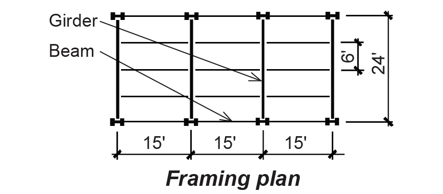
Problem definition. Using A992 steel, design the typical beam and girder for the library stack area shown in Figure 4.27. Use the generic dead load for steel floor systems. Assume that the beams are continuously braced by the floor deck, and that the girders are braced only by the beams framing into them.
Solution overview. Find loads; compute maximum bending moment and shear force; use appropriate tables to select beams for bending; then check for shear and deflection.
Problem solution
Find loads: From Appendix Table A-2.1, the dead load, D = 47 psf.
From Appendix Table A-2.2, the live load, L = 150 psf.
Beam design
1. Create load, shear and moment diagrams as shown in Figure 4.28 to determine critical (i.e., maximum) shear force and bending moment. The total distributed load, w = (dead + live)(tributary area for 1 linear foot) = (47 + 150)(6) = 1182 lb/ft = 1.18 kips/ft. Live load reduction would not apply even if the "influence" area was not less than 400 ft2, because of the library stack occupancy (i.e., the probability of full loading makes live load reduction a dangerous assumption).
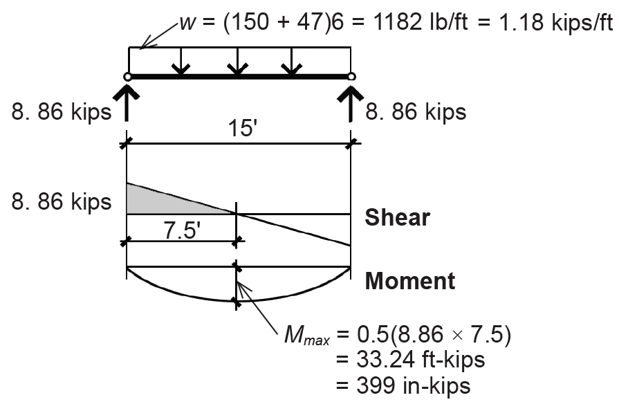
2. Find allowable bending stress: since the beam is laterally braced by the floor deck and the cross section is assumed to be compact, use Equation 4.12 to find Zreq = ΩMmax /Fy = 1.67Mmax /Fy. From Appendix Table A-4.1, Fy = 50 ksi for A992 steel, so Zreq = 1.67(399)/50 = 13.33 in3.
3. From Appendix Table A-4.15, select a W12 × 14 with actual Zx = 17.4 in3 ≥ Zreq. This section is, by definition, OK for bending.
4. Check section for shear: from Appendix Table A-4.3, the actual web area, Aw = d × tw = 11.9 × 0.20 = 2.38 in2.
5. From Equation 4.14, the required Aw = V/Fv = 8.86/(0.36 × 50) = 0.49 in2 where, from Appendix Table A-4.2, the allowable shear stress, Fv = 0.36Fy (and not the usual value of Fv = 0.40Fy) because the beam web is unusually slender. Beams requiring such reduced allowable shear stresses are noted in Appendix Table A-4.3. Since the actual web area is greater than the required web area, the beam is OK for shear.
6. From Appendix Table A-1.3 (also summarized in Appendix Table A-4.17), find the allowable total-load deflection for a floor beam: ΔTallow = span/240 = 12(15)/240 = 0.75 in. and the allowable live-load deflection for a floor joist: ΔLallow = span/360 = 12(15)/360 = 0.5 in.
7. From Appendix Table A-4.17, the actual total load deflection, ΔTact = CP(L/12)3/(EI) where:
C = 22.46.
L = 15 × 12 = 180 in. (the term, L, is used for both span and live load).
P = w(L/12) = (150 + 47)(6)(180/12) = 17,730 lb = 17.73 kips.
E = 29,000 ksi (Appendix Table A-4.1, Note 1).
I = 88.6 in4 (Appendix Table A-4.3).
ΔTact = 22.46(17.73)(180/12)3/(29,000 × 88.6) = 0.523 in.
Since ΔTact = 0.523 in. ≤ ΔTallow = 0.75 in., the beam is OK for total-load deflection.
8. From Appendix Table A-4.17, the actual live load deflection, ΔLact = CP(L/12)3/(EI) where:
C = 22.46.
L = 15 × 12 = 180 in.
P = w(L/12) = (150 × 6)(180/12) = 13500 lb = 13.5 kips (Use live load only!).
E = 29,000 ksi (Appendix Table A-4.1, Note 1).
I = 88.6 in4 (Appendix Table A-4.3).
ΔLact = 22.46(13.5)(180/12)3/(29,000 × 88.6) = 0.398 in.
Since ΔLact = 0.398 in. ≤ ΔLallow = 0.5 in., the beam is OK for live-load deflection.
9. Conclusion: The W12 × 14 section is OK for bending, shear and deflection. Therefore it is acceptable.
Girder design
1. Create load, shear and moment diagrams as shown in Figure 4.29 to determine the critical (i.e., maximum) shear force and bending moment. Each concentrated load is twice the typical beam reaction, or 17.73 kips. Alternatively, compute using tributary areas; that is, P = (47 + 150)(15 × 6) = 17,730 lb = 17.73 kips. Live load reduction does not apply even though the "influence" area is greater than 400 ft2, because of the library stack occupancy (i.e., the probability of full loading makes live load reduction a dangerous assumption).
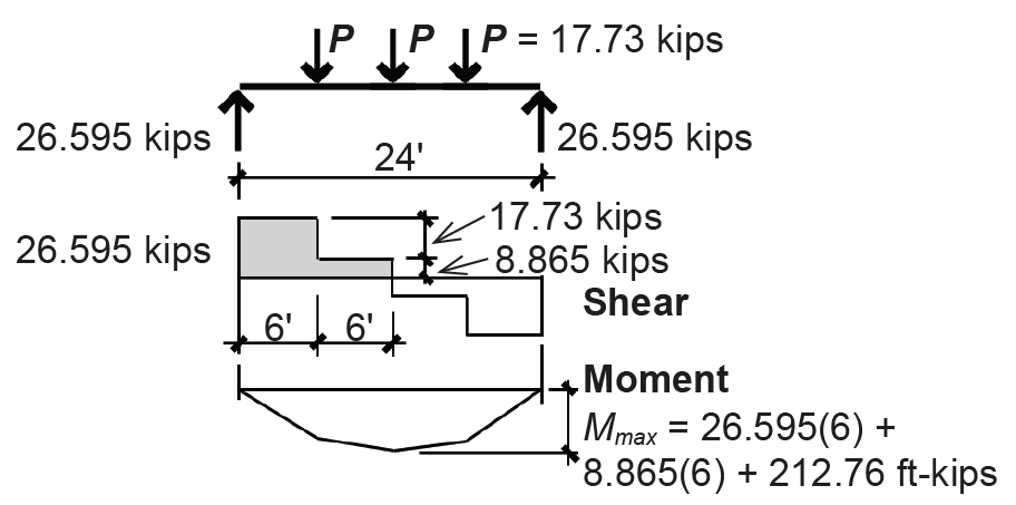
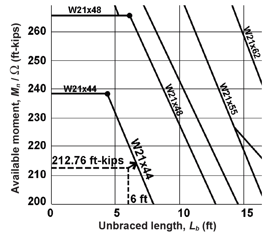
2. Find allowable bending stress: The girder is not continuously braced by the floor deck; rather, it is braced every 6 ft by the beams framing into it, so the unbraced length, Lb = 6 ft. Use Appendix Table A-4.16 to directly find the lightest cross section for bending, based on Mmax = 212.76 ft-kips, Lb = 6 ft, and assuming (conservatively) that the "lateral-torsional buckling modifier," Cb = 1.0. Find the intersection of moment and unbraced length (follow the dotted lines shown in Figure 4.30) and then move up or to the right to the first solid line representing the available moment capacity of wide-flange beams. Select a W21 × 44.
3. Check section for shear: from Appendix Table A-4.3, the actual web area, Aw = d × tw = 20.7 × 0.35 = 7.25 in2.
4. From Equation 4.14, the required Aw = V/Fv = 26.595/(0.40 × 50) = 1.33 in2 where, from Appendix Table A-4.2, the allowable shear stress, Fv = 0.40Fy (the usual value of Fv = 0.40Fy applies in this case). Since the actual web area is greater than the required web area, the beam is OK for shear.
5. From Appendix Table A-1.3 (also summarized in Appendix Table A-4.17), find the allowable total-load deflection for a floor beam, ΔTallow = span/240 = 12(24)/240 = 1.2 in., and the allowable live-load deflection for a floor joist, ΔLallow = span/360 = 12(24)/360 = 0.8 in.
6. From Appendix Table A-4.17, the actual total-load deflection, ΔTact = CP(L/12)3/(EI) where:
C = 85.54.
L = 24 × 12 = 288 in.
P = (47 + 150)(15 × 6) = 17,730 lb = 17.73 kips.
E = 29,000 ksi (Appendix Table A-4.1, Note 1).
I = 843 in4 (Appendix Table A-4.3).
ΔTact = 85.54(17.73)(288/12)3/(29,000 × 843) = 0.86 in.
Since ΔTact = 0.86 in. ≤ ΔTallow = 1.2 in., beam is OK for total-load deflection.
7. From Appendix Table A-4.17, the actual live-load deflection, ΔLact = CP(L/12)3/(EI) where:
C = 85.54.
L = 24 × 12 = 288 in.
P = 150(15 × 6) = 13,500 lb = 13.5 kips (Use live load only!).
E = 29,000 ksi (Appendix Table A-4.1, Note 1).
I = 843 in4 (Appendix Table A-4.3).
ΔLact = 85.54(13.5)(288/12)3/(29,000 × 843) = 0.65 in.
Since ΔLact = 0.65 in. ≤ ΔLallow = 0.80 in., beam is OK for live-load deflection.
8. Conclusion: The W21 × 44 section is OK for bending, shear and deflection. Therefore it is acceptable.
Problem definition. Determine whether an HSS12 × 4 × 1/4 can be used as a typical beam for the library stack area shown in Example 4.6.
Solution overview. Find loads; compute maximum bending moment and shear force; check beam for bending, shear, and deflection.
Problem solution
1. Find loads and moment (same as Example 4.6):
The dead load, D = 47 psf.
The live load, L = 150 psf
Maximum moment, Mmax = 399 in-kips
2. Find allowable bending stress: Since the beam is laterally braced by the floor deck and the cross section is assumed to be compact, use Equation 4.12 to find Zreq = ΩMmax/Fy = 1.67Mmax/ Fy. From Appendix Table A-4.1, Fy = 46 ksi for HSS rectangular shapes (A500 grade B), so Zreq = 1.67(399)/46 = 14.49 in3.
3. From Appendix Table A-4.6, the actual plastic section modulus for an HSS12 × 4 × 1/4, Zx = 25.6 in3. Since the actual Zx is greater than Zreq, this HSS section is OK for bending.
4. Check section for shear: from Appendix Table A-4.2 (Note 3), the web area, Aw is taken as 2ht (where t is the wall thickness of the web and h can be assumed to equal the nominal depth minus 3t). From Appendix Table A-4.4, this web area, Aw = 2ht = 2(12 – 3 × 0.233)(0.233) = 5.27 in2.
5. From Equation 4.14, the required Aw = V/Fv = 8.86/(0.36 × 50) = 0.49 in2 where, from Appendix Table A-4.2, the allowable shear stress, Fv = 0.36Fy (and not the value of Fv = 0.40Fy used for most wide-flange beams). Since the actual web area is greater than the required web area, the HSS beam is OK for shear.
6. From Appendix Table A-1.3 (also summarized in Appendix Table A-4.17), find the allowable total-load deflection for a floor beam: ΔTallow = span/240 = 12(15)/240 = 0.75 in.; and the allowable live-load deflection for a floor joist: ΔLallow = span/360 = 12(15)/360 = 0.5 in.
7. From Appendix Table A-4.17, the actual total-load deflection, ΔTact = CP(L/12)3/(EI) where:
C = 22.46.
L = 15 × 12 = 180 in.
P = w(L/12) = (47 + 150)(6)(180/12) = 17,730 lb = 17.73 kips.
E = 29,000 ksi (Appendix Table A-4.1, Note 1).
I = 119 in4 (Appendix Table A-4.6).
ΔTact = 22.46(17.73)(180/12)3/(29,000 × 119) = 0.389 in.
Since ΔTact = 0.389 in. ≤ ΔTallow = 0.75 in., the HSS beam is OK for total-load deflection.
8. From Appendix Table A-4.17, the actual live-load deflection, ΔLact = CP(L/12)3/(EI) where:
C = 22.46.
L = 15 × 12 = 180 in.
P = w(L/12) = (150 × 6)(180/12) = 13500 lb = 13.5 kips (Use live load only!).
E = 29,000 ksi (Appendix Table A-4.1, Note 1).
I = 119 in4 (Appendix Table A-4.6).
ΔTact = 22.46(13.5)(180/12)3/(29,000 × 119) = 0.300 in.
Since ΔLact = 0.300 in. ≤ ΔLallow = 0.5 in., the HSS beam is OK for live-load deflection.
9. Conclusion: The HSS12 × 4 × 1/4 section is OK for bending, shear and deflection. Therefore it is acceptable.
© 2020 Jonathan Ochshorn; all rights reserved. This section first posted November 15, 2020; last updated November 15, 2020.