
Contents | 1. Introduction to structural design | 2. Loads | 3. Wood |
Introduction to steel | Material properties | Sectional properties | Design approaches | Construction systems | Tension elements |
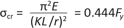
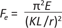
Steel columns with high slenderness ratios are designed using the Euler buckling equation, while "fatter" columns, which buckle inelastically or crush without buckling, are designed according to formulas corresponding to test results. Residual compressive stresses within hot-rolled steel sections precipitate this inelastic buckling, as they cause local yielding to occur sooner than might otherwise be expected. Unlike timber column design, the two design equations corresponding to elastic and inelastic buckling have not been integrated into a single unified formula, so the underlying rationale remains more apparent. The slenderness ratio dividing elastic from inelastic buckling is set, somewhat arbitrarily, at the point where the Euler critical buckling stress equals 0.444 times the yield stress; i.e., at the stress:
This particular slenderness ratio separating elastic from inelastic buckling is found by solving for (KL/r) in Equation 4.7:
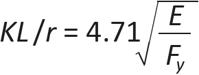
For Fy = 50 ksi, the value of KL/r is 113; for Fy = 36 ksi, the value is 134. For a slender column with a slenderness ratio greater than this separating value, elastic buckling is assumed, and the allowable ("available") axial compressive stress, based on Euler's equation (multiplied by a factor of 0.877, and divided by a safety factor, Ω = 1.67), is:
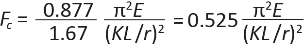
The coefficient, 0.525, in Equation 4.9 corresponds to the safety factor of 12/23 previously used for elastic buckling of steel columns.
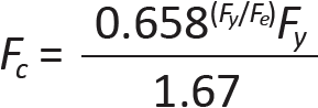
Where KL/r is less than the value separating elastic from inelastic buckling, inelastic buckling governs, and the allowable ("available") axial compressive stress is found by dividing the critical stress for inelastic buckling by the same factor of safety, Ω = 1.67:
In this equation, Fe is the elastic buckling stress shown in Equation 1.19; that is:
The slenderness ratio, KL/r, should not exceed 200 for steel axial compression elements. Values for K are shown in Appendix Table A-1.2. We are also assuming that compression elements are proportioned so that local buckling of their flanges or web does not occur; this requires that the compression element (typically a column) is not defined as slender. Wide-flange elements that are determined to be slender for compression are noted in Appendix Table A-4.3. Their design, involving calculations that effectively reduce the load they can safely carry, is beyond the scope of this discussion.
The two curves representing allowable stresses for elastic and inelastic buckling make a smooth transition at the slenderness ratio separating them, as shown in Figure 4.18.
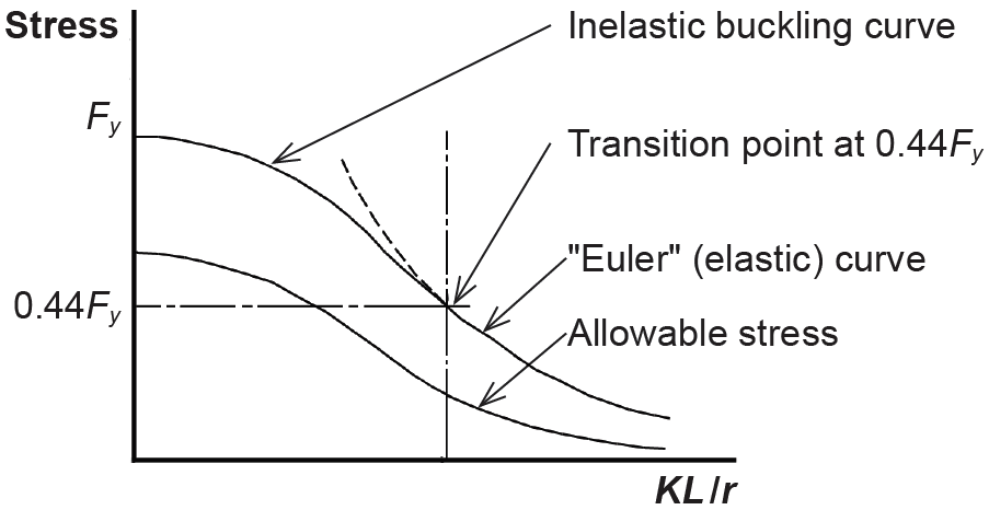
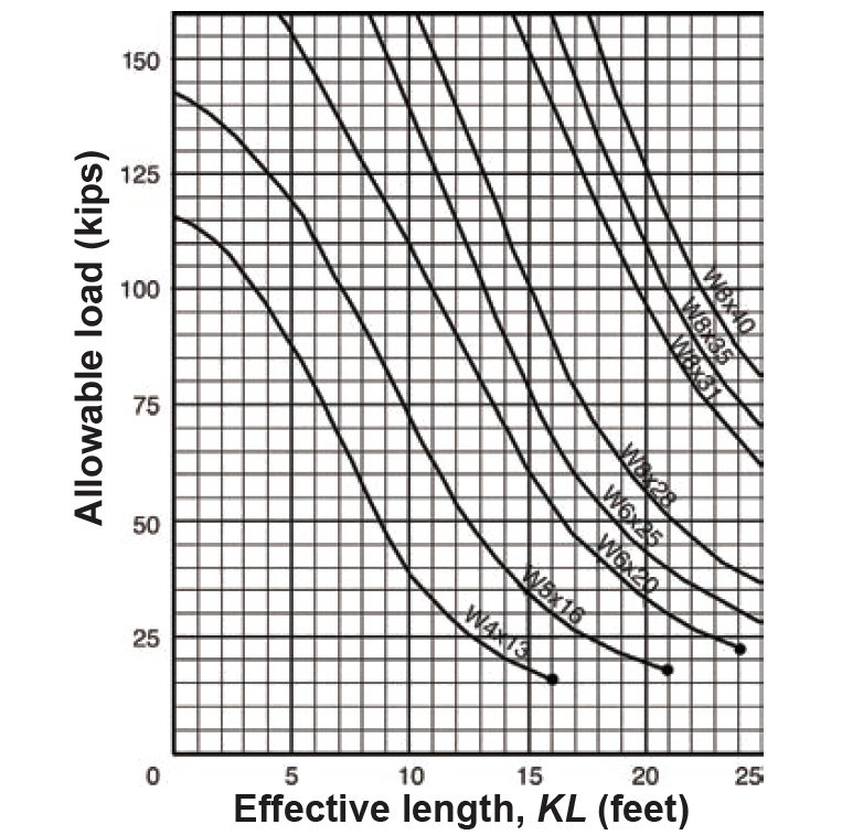
Rather than apply these equations to the solution of axial compression problems in steel, allowable stress tables (for analysis, Appendix Tables A-4.11 through A-4.14) or allowable load tables (for design, Appendix Table A-4.10) are more often used. If values for allowable load are plotted instead of tabulated, the curves have the same pattern schematically represented in Figure 4.18. Examples of these axial column load curves are shown in Figure 4.19.
Problem definition. Find the capacity (allowable load) of a W14 × 61 pin-ended column with an effective length of 10 ft. Assume A36 steel.
Solution overview. Find relevant section properties; compute slenderness ratio; find allowable stress and capacity.
Problem solution
1. From Appendix Table A-4.3, rmin = 2.45 in.
2. Compute slenderness ratio:
a. From Appendix Table A-1.2, the effective length coefficient, K = 1.0.
b. The effective length, L = 10.0 × 12 = 120 in.
c. KL/rmin = (1.0)(120)/2.45 = 48.98. Round up to 49.
3. From Appendix Table A-4.14, the allowable stress: Fc = 19.0 ksi.
4. Find capacity: From Appendix Table A-4.3, the area of the steel column, A = 17.9 in2. The capacity, P = Fc × A = 19.0(17.9) = 340 kips.
From Equation 4.8, the slenderness ratio separating elastic and inelastic column behavior is 134 for A36 steel. The column analyzed in Example 4.3 has a slenderness ratio of 48.98, which is less than this separating value; therefore, it fails inelastically. Using Equation 4.10 to determine the "inelastic" allowable stress, we get the same result as was obtained in the example. The calculations are as follows, using Fy = 36 ksi:
From Equation 4.11, Fe = π2(29,000)/(48.982) = 119.3. Then, from Equation 4.10:
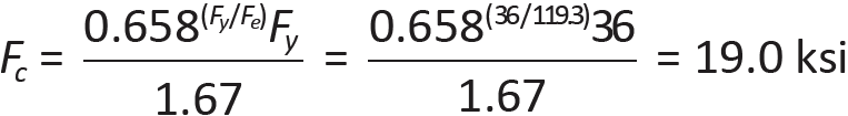
It can be seen that this is the same allowable stress as was obtained in Example 4.3.
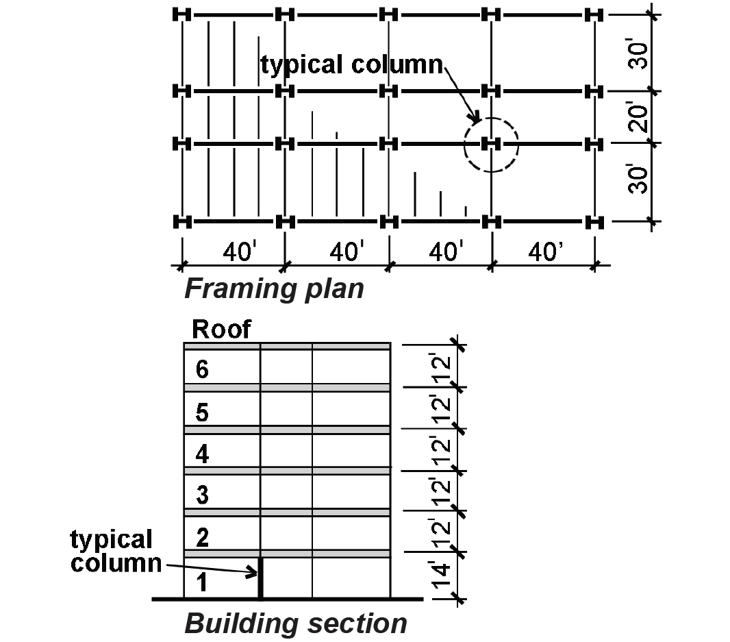
Problem definition. Select the lightest (most economical) wide-flange section for the first-floor column shown in Figure 4.20. Assume office occupancy; a roof (construction) live load of 20 psf; a typical steel floor system; and an allowance for steel stud partitions. Assume pin-ended (simple) connections. Use A992 steel.
Solution overview. Find total load on column; find effective length; select lightest section.
Problem solution
1. Find total column load:
a. From Appendix Table A-2.2, the live load (L) for office occupancy = 50 psf.
b. From Appendix Table A-2.1, the typical dead load (D) = 47 psf (steel floor system, etc.) + 8 psf (steel stud partition allowance) = 55 psf.
c. The roof construction live load (Lr) = 20 psf, according to the Problem Definition.
d. Find tributary area (see Figure 1.5): The column's tributary area is 25 ft × 40 ft = 1000 ft2 per floor, or 5000 ft2 for the five levels on which occupancy live loads are computed (excluding the roof).
e. Using Appendix Table A-2.2, compute the reduced live load; the live load reduction factor is: 0.25 + 15/ = 0.36, but no reduction less than 0.40 is permitted. Therefore, the live load can be reduced to 0.40 × 50 = 20 psf for the first-floor column under consideration.
f. Using Appendix Table A-2.7 for allowable stress design, find the total column load, accounting for reductions due to load combinations:
L = (25 ft × 40 ft) × (20 psf) × 5 floors = 100,000 lb
D = (25ft × 40 ft) × (55 psf) × 6 floors = 330,000 lb
Lr = (25ft × 40 ft) × (20 psf) × 1 floor = 20,000 lb
For the three loads potentially present, only two load combinations need be considered (the others listed will produce less severe effects). For the second load combination, wind or seismic effects on the column may also be considered. However, in this example, we assume that the column is not part of the lateral force-resisting system for wind or seismic, and that any negative (uplift) wind load on the roof can be conservatively ignored. The two relevant load combinations to consider are as follows:
D + L = 330,000 + 100,000 = 430,000 lb
D + 0.75L + 0.75Lr = 330,000 + 0.75(100,000) + 0.75(20,000) = 330,000 + 75,000 + 15,000 = 420,000 lb.
The first case governs; therefore the total column load = 430,000 lb = 430 kips.
2. Using Appendix Table A-1.2, find the effective length: KL = (1.0)(14) = 14 ft.
3. Select the most economical section:
a. Using Appendix Table A-4.10, pick the lightest acceptable section from each "nominal depth" group (i.e., one W8, one W10, one W12, and so on), to assemble a group of "likely candidates." Some columns are clearly either to small or too large; the three possible candidates for a load of 430 kips and an effective length of 14 ft. are:
• W10 × 68 can support 440 kips
• W12 × 65 can support 456 kips
• W14 × 74 can support 466 kips
b. Choose lightest section: The W12 × 65 is the most economical since its weight per linear foot (65 pounds) is smallest.
To check the result in Example 4.4, first determine the slenderness ratio of the W12 × 65, finding the minimum (y-axis) radius of gyration, r = 3.02 in., from Appendix Table A-4.3. Then, KL/r = (1.0)(14 × 12)/3.02 = 55.63. From Equation 4.8, the slenderness ratio separating elastic from inelastic behavior for A992 steel is 113, so the column fails inelastically. Using Equation 4.10 to determine the "inelastic" allowable stress, we get the same result as was obtained in the example. The calculations are as follows, using Fy = 50 ksi:
From Equation 4.11, Fe = π2(29,000)/(55.632) = 92.5. Then, from Equation 4.10:
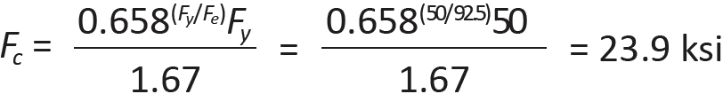
From Appendix Table A-4.3, the area of the W12 × 65, A = 19.1 in2. Therefore, the capacity, P = Fc × A = 23.9 × 19.1 = 456 kips, the same value found in Example 4.4.
© 2020 Jonathan Ochshorn; all rights reserved. This section first posted November 15, 2020; last updated November 15, 2020.