
Contents | 1. Introduction to structural design | 2. Loads | 3. Wood |
Introduction to steel | Material properties | Sectional properties | Design approaches | Construction systems | Tension elements | Columns | Beams | Connections |
Table A-4.1: Steel properties1
| Category | ASTM designation | Yield stress, Fy (ksi) | (Ultimate) tensile stress, Fu (ksi) | Preferred for these shapes | |
|---|---|---|---|---|---|
| Carbon | A36 A500 Gr. B A500 Gr. B A53 Gr. B |
36 42 46 235 |
58 58 58 60 |
M, S, C, MC, L, plates4 and bars HSS round5 HSS rectangular5 Pipe | |
| High-strength, low-alloy | A992 A572 Gr. 50 |
50 50 |
65 65 |
3W HP | |
| Corrosion resistant, high-strength, low-alloy | A588 A242 |
50 42–50 |
70 63–70 |
||
| Low alloy reinforcing bars | A615 | 40 60 75 |
60 90 100 |
Rebar | |
| Bolts | F3125 | A325 | n/a | 120 | High-strength bolts, 0.5 – 1.5 in. diameter |
| A490 | n/a | 150 | High-strength bolts, 0.5 – 1.5 in. diameter | ||
| F3043 | n/a | 200 | Check availability for these bolts, 1 – 1.25 in. diameter | ||
| A307 Gr. A | n/a | 60 | Common bolts | ||
| Cold-formed | A653 Gr. 33 | 33 | 45 | Connector plates4 in wood construction | |
Notes:
1. The modulus of elasticity, E, for these steels can be taken as 29,000 ksi.
2. Steel with Fy = 35 ksi may be designed as if the yield stress is Fy = 36 ksi.
3. W-shapes have formerly been specified in A36; current practice in the U.S. is to use A992 with Fy = 50 ksi.
4. In wood fastener design, the dowel bearing strength of connector plates, Fe equals 1.5Fu (for A36 hot-rolled steel) and 1.375Fu (for A653 GR 33 cold-formed steel). These values are 1.6 times less than those permitted in steel structures so that they can be used in yield limit equations for wood members that have load duration adjustments (adjustments that may be as high as 1.6 for wind or seismic).
5. HSS can also be specified by ASTM A1085 and A1065, which follow somewhat different rules and are not considered in this text.
Table A-4.2: Steel allowable stresses and available strengths
| Type of structural action | Allowable stress1 (same units as Fy or Fu) | Available strength limit states (with safety factor, Ω)4 |
|---|---|---|
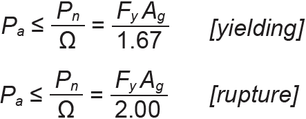
| Tension | Ftgross = 0.60Fy (yielding) Ftnet = 0.50Fu (rupture) |
 |
| Compression | See Tables A-4.11 through A-4.14 (analysis) or A-4.10 (design) | |
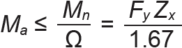
| Bending2, assuming laterally braced, compact section | Fb = 0.60Fy (used with plastic section modulus, Zx) orFb = 0.66Fy (used with elastic section modulus, Sx) |
 The available strength method has no official limit state for the elastic moment |
| Shear3 | Fv = 0.40Fy | 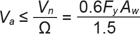 |
Notes:
1. Allowable stresses, although no longer officially sanctioned by the American Institute of Steel Construction, result in the same values that are obtained when considering available strength, except in the case of bending. For bending, the limit state defined by the elastic moment, formerly the basis of allowable stress design, is no longer applicable, although it can still be used with somewhat conservative results for laterally-braced, compact sections. On the other hand, an allowable stress equation can be formulated based on the plastic section modulus that is equivalent to the available strength equation for laterally-braced, compact sections.
2. The allowable stress for bending, 0.66Fb, used with the elastic section modulus, Sx, gives a generally conservative value compared with using Ω = 1.67 and the plastic section modulus, Zx. To reconcile these two different safety factors, it is necessary to approximate the ratio of Zx/Sx, which varies depending upon the cross section. This ratio can be taken conservatively as 1.1 for W shapes; therefore, Zx = 1.1Sx, and the allowable moment, Mp /Ω = FyZx/Ω = 1.1FySx/Ω = 1.1FySx/1.67 = 0.66FbSx, which corresponds to the assumptions used for an allowable bending stress.
3. Both the allowable stress and available strength values for shear assume ![]() -shaped rolled members meeting the slenderness criteria for beam webs. For beam webs that do not meet slenderness criteria for shear, a reduced allowable shear stress, Fv = 0.36Fy, is used. This is equivalent to using an increased allowable strength design safety factor, Ω = 1.67, and applies to the following W-shapes: W12 × 14, W16 × 26, W24 × 55, W30 × 90, W33 × 118, W36 × 135, W40 × 149, and W44 × 230. For the rectangular HSS listed in Appendix Table A-4.6, the reduced shear stress, Fv = 0.36Fy, is also used, with a web area, Aw, equal to 2ht (where t is the wall thickness of the web and h can be assumed to equal the nominal depth minus 3t). The value for the coefficient Cv is equal to 1.0 for all W-shapes, and is not included in the shear equations. For cross sections with very thin webs, this coefficient needs to be considered.
-shaped rolled members meeting the slenderness criteria for beam webs. For beam webs that do not meet slenderness criteria for shear, a reduced allowable shear stress, Fv = 0.36Fy, is used. This is equivalent to using an increased allowable strength design safety factor, Ω = 1.67, and applies to the following W-shapes: W12 × 14, W16 × 26, W24 × 55, W30 × 90, W33 × 118, W36 × 135, W40 × 149, and W44 × 230. For the rectangular HSS listed in Appendix Table A-4.6, the reduced shear stress, Fv = 0.36Fy, is also used, with a web area, Aw, equal to 2ht (where t is the wall thickness of the web and h can be assumed to equal the nominal depth minus 3t). The value for the coefficient Cv is equal to 1.0 for all W-shapes, and is not included in the shear equations. For cross sections with very thin webs, this coefficient needs to be considered.
4. In these equations for various limit states, the subscript a refers to the available strength of the cross section, that is, the strength that is considered safe. The subscript n refers to the nominal strength of the cross section, that is, the actual limit state of the material. In other words, Pa is equivalent to the maximum tension force that the cross section can safely sustain; Ma is equivalent to the maximum bending moment that the cross section can safely sustain; and Va is equivalent to the maximum shear force that the cross section can safely sustain.
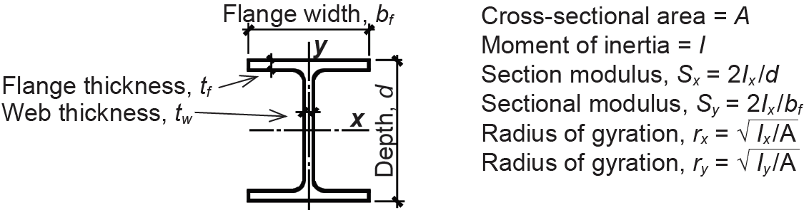
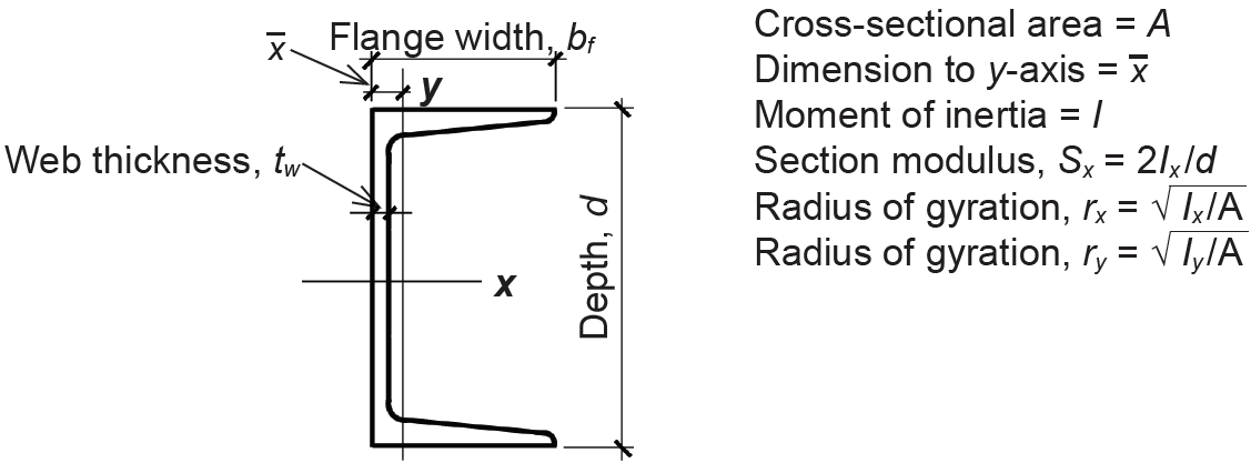
Table A-4.3: Dimensions and properties of steel W sections5
 | ||||||||||||||||
| Designa- tion |
A (in2) |
d (in.) |
tw (in.) |
bf (in.) |
tf (in.) |
Sx (in3) |
Zx (in3) |
Ix (in4) |
Iy (in4) |
ry (in.) | ||||||
|---|---|---|---|---|---|---|---|---|---|---|---|---|---|---|---|---|
| W4 × 13 | 3.83 | 4.16 | 0.280 | 4.06 | 0.345 | 5.46 | 6.28 | 11.3 | 3.86 | 1.00 | ||||||
| W5 × 16 W5 × 19 |
4.71 5.56 |
5.01 5.15 |
0.240 0.270 |
5.00 5.03 |
0.360 0.430 |
8.55 10.2 |
9.63 11.6 |
21.4 26.3 |
7.51 9.13 |
1.26 1.28 | ||||||
| W6 × 8.52 W6 × 92 W6 × 12 W6 × 16 |
2.52 2.68 3.55 4.74 |
5.83 5.90 6.03 6.28 |
0.170 0.170 0.230 0.260 |
3.94 3.94 4.00 4.03 |
0.195 0.215 0.280 0.405 |
5.10 5.56 7.31 10.2 |
5.73 6.23 8.30 11.7 |
14.9 16.4 22.1 32.1 |
1.99 2.20 2.99 4.43 |
0.890 0.905 0.918 0.967 | ||||||
| W6 × 151 W6 × 20 W6 × 25 |
4.43 5.87 7.34 |
5.99 6.20 6.38 |
0.230 0.260 0.320 |
5.99 6.02 6.08 |
0.260 0.365 0.455 |
9.72 13.4 16.7 |
10.8 14.9 18.9 |
29.1 41.4 53.4 |
9.32 13.3 17.1 |
1.45 1.50 1.52 | ||||||
| W8 × 102,4 W8 × 13 W8 × 15 |
2.96 3.84 4.44 |
7.89 7.99 8.11 |
0.170 0.230 0.245 |
3.94 4.00 4.02 |
0.205 0.255 0.315 |
7.81 9.91 11.8 |
8.87 11.4 13.6 |
30.8 39.6 48.0 |
2.09 2.73 3.41 |
0.841 0.843 0.876 | ||||||
| W8 × 18 W8 × 21 |
5.26 6.16 |
8.14 8.28 |
0.230 0.250 |
5.250 5.270 |
0.330 0.400 |
15.2 18.2 |
17.0 20.4 |
61.9 75.3 |
7.97 9.77 |
1.23 1.26 | ||||||
| W8 × 24 W8 × 28 |
7.08 8.25 |
7.93 8.06 |
0.245 0.285 |
6.50 6.54 |
0.400 0.465 |
20.9 24.3 |
23.1 27.2 |
82.7 98.0 |
18.3 21.7 |
1.61 1.62 | ||||||
| W8 × 312 W8 × 35 W8 × 40 W8 × 48 W8 × 58 W8 × 67 |
9.13 10.3 11.7 14.1 17.1 19.7 |
8.00 8.12 8.25 8.50 8.75 9.00 |
0.285 0.310 0.360 0.400 0.510 0.570 |
8.00 8.02 8.07 8.11 8.22 8.28 |
0.435 0.495 0.560 0.685 0.810 0.935 |
27.5 31.2 35.5 43.2 52.0 60.4 |
30.4 34.7 39.8 49.0 59.8 70.1 |
110 127 146 184 228 272 |
37.1 42.6 49.1 60.9 75.1 88.6 |
2.02 2.03 2.04 2.08 2.10 2.12 | ||||||
| W10 × 122,4 W10 × 154 W10 × 174 W10 × 19 |
3.54 4.41 4.99 5.62 |
9.87 10.0 10.1 10.2 |
0.190 0.230 0.240 0.250 |
3.96 4.00 4.01 4.02 |
0.210 0.270 0.330 0.395 |
10.9 13.8 16.2 18.8 |
12.6 16.0 18.7 21.6 |
53.8 68.9 81.9 96.3 |
2.18 2.89 3.56 4.29 |
0.785 0.810 0.845 0.874 | ||||||
| W10 × 224 W10 × 26 W10 × 30 |
6.49 7.61 8.84 |
10.2 10.3 10.5 |
0.240 0.260 0.300 |
5.75 5.77 5.81 |
0.360 0.440 0.510 |
23.2 27.9 32.4 |
26.0 31.3 36.6 |
118 144 170 |
11.4 14.1 16.7 |
1.33 1.36 1.37 | ||||||
| W10 × 33 W10 × 39 W10 × 45 |
9.71 11.5 13.3 |
9.73 9.92 10.10 |
0.290 0.315 0.350 |
7.96 7.99 8.02 |
0.435 0.530 0.620 |
35.0 42.1 49.1 |
38.8 46.8 54.9 |
171 209 248 |
36.6 45.0 53.4 |
1.94 1.98 2.01 | ||||||
| W10 × 49 W10 × 54 W10 × 60 W10 × 68 W10 × 77 W10 × 88 W10 × 100 W10 × 112 |
14.4 15.8 17.7 19.9 22.7 26.0 29.3 32.9 |
10.0 10.1 10.2 10.4 10.6 10.8 11.1 11.4 |
0.340 0.370 0.420 0.470 0.530 0.605 0.680 0.755 |
10.0 10.0 10.1 10.1 10.2 10.3 10.3 10.4 |
0.560 0.615 0.680 0.770 0.870 0.990 1.120 1.250 |
54.6 60.0 66.7 75.7 85.9 98.5 112 126 |
60.4 66.6 74.6 85.3 97.6 113 130 147 |
272 303 341 394 455 534 623 716 |
93.4 103 116 134 154 179 207 236 |
2.54 2.56 2.57 2.59 2.60 2.63 2.65 2.68 | ||||||
| W12 × 143,4 W12 × 164 W12 × 194 W12 × 224 |
4.16 4.71 5.57 6.48 |
11.9 12.0 12.2 12.3 |
0.200 0.220 0.235 0.260 |
3.97 3.99 4.01 4.03 |
0.225 0.265 0.350 0.425 |
14.9 17.1 21.3 25.4 |
17.4 20.1 24.7 29.3 |
88.6 103 130 156 |
2.36 2.82 3.76 4.66 |
0.753 0.773 0.822 0.848 | ||||||
| Designa- tion |
A (in2) |
d (in.) |
tw (in.) |
bf (in.) |
tf (in.) |
Sx (in3) |
Zx (in3) |
Ix (in4) |
Iy (in4) |
ry (in.) | ||||||
| W12 × 264 W12 × 304 W12 × 354 |
7.65 8.79 10.3 |
12.2 12.3 12.5 |
0.230 0.260 0.300 |
6.49 6.52 6.56 |
0.380 0.440 0.520 |
33.4 38.6 45.6 |
37.2 43.1 51.2 |
204 238 285 |
17.3 20.3 24.5 |
1.51 1.52 1.54 | ||||||
| W12 × 40 W12 × 45 W12 × 50 |
11.7 13.1 14.6 |
11.9 12.1 12.2 |
0.295 0.335 0.370 |
8.01 8.05 8.08 |
0.515 0.575 0.640 |
51.5 57.7 64.2 |
57.0 64.2 71.9 |
307 348 391 |
44.1 50.0 56.3 |
1.94 1.95 1.96 | ||||||
| W12 × 53 W12 × 58 |
15.6 17.0 |
12.1 12.2 |
0.345 0.360 |
10.0 10.0 |
0.575 0.640 |
70.6 78.0 |
77.9 86.4 |
425 475 |
95.8 107 |
2.48 2.51 | ||||||
| W12 × 652 W12 × 72 W12 × 79 W12 × 87 W12 × 96 W12 × 106 W12 × 120 W12 × 136 W12 × 152 W12 × 170 W12 × 190 W12 × 210 W12 × 230 W12 × 252 W12 × 279 W12 × 305 W12 × 336 |
19.1 21.1 23.2 25.6 28.2 31.2 35.2 39.9 44.7 50.0 56.0 61.8 67.7 74.1 81.9 89.5 98.9 |
12.1 12.3 12.4 12.5 12.7 12.9 13.1 13.4 13.7 14.0 14.4 14.7 15.1 15.4 15.9 16.3 16.8 |
0.390 0.430 0.470 0.515 0.550 0.610 0.710 0.790 0.870 0.960 1.06 1.18 1.29 1.40 1.53 1.63 1.78 |
12.0 12.0 12.1 12.1 12.2 12.2 12.3 12.4 12.5 12.6 12.7 12.8 12.9 13.0 13.1 13.2 13.4 |
0.605 0.670 0.735 0.810 0.900 0.990 1.11 1.25 1.40 1.56 1.74 1.90 2.07 2.25 2.47 2.71 2.96 |
87.9 97.4 107 118 131 145 163 186 209 235 263 292 321 353 393 435 483 |
96.8 108 119 132 147 164 186 214 243 275 311 348 386 428 481 537 603 |
533 597 662 740 833 933 1070 1240 1430 1650 1890 2140 2420 2720 3110 3550 4060 |
174 195 216 241 270 301 345 398 454 517 589 664 742 828 937 1050 1190 |
3.02 3.04 3.05 3.07 3.09 3.11 3.13 3.16 3.19 3.22 3.25 3.28 3.31 3.34 3.38 3.42 3.47 | ||||||
| W14 × 224 W14 × 264 |
6.49 7.69 |
13.7 13.9 |
0.230 0.255 |
5.00 5.03 |
0.335 0.420 |
29.0 35.3 |
33.2 40.2 |
199 245 |
7.00 8.91 |
1.04 1.08 | ||||||
| W14 × 304 W14 × 344 W14 × 384 |
8.85 10.0 11.2 |
13.8 14.0 14.1 |
0.270 0.285 0.310 |
6.73 6.75 6.77 |
0.385 0.455 0.515 |
42.0 48.6 54.6 |
47.3 54.6 61.5 |
291 340 385 |
19.6 23.3 26.7 |
1.49 1.53 1.55 | ||||||
| W14 × 434 W14 × 48 W14 × 53 |
12.6 14.1 15.6 |
13.7 13.8 13.9 |
0.305 0.340 0.370 |
8.00 8.03 8.06 |
0.530 0.595 0.660 |
62.6 70.2 77.8 |
69.6 78.4 87.1 |
428 484 541 |
45.2 51.4 57.7 |
1.89 1.91 1.92 | ||||||
| W14 × 61 W14 × 68 W14 × 74 W14 × 82 |
17.9 20.0 21.8 24.0 |
13.9 14.0 14.2 14.3 |
0.375 0.415 0.450 0.510 |
10.0 10.0 10.1 10.1 |
0.645 0.720 0.785 0.855 |
92.1 103 112 123 |
102 115 126 139 |
640 722 795 881 |
107 121 134 148 |
2.45 2.46 2.48 2.48 | ||||||
| W14 × 902 W14 × 992 W14 × 109 W14 × 120 W14 × 132 |
26.5 29.1 32.0 35.3 38.8 |
14.0 14.2 14.3 14.5 14.7 |
0.440 0.485 0.525 0.590 0.645 |
14.5 14.6 14.6 14.7 14.7 |
0.710 0.780 0.860 0.940 1.03 |
143 157 173 190 209 |
157 173 192 212 234 |
999 1110 1240 1380 1530 |
362 402 447 495 548 |
3.70 3.71 3.73 3.74 3.76 | ||||||
| Designa- tion |
A (in2) |
d (in.) |
tw (in.) |
bf (in.) |
tf (in.) |
Sx (in3) |
Zx (in3) |
Ix (in4) |
Iy (in4) |
ry (in.) | ||||||
| W14 × 145 W14 × 159 W14 × 176 W14 × 193 W14 × 211 W14 × 233 W14 × 257 W14 × 283 W14 × 311 W14 × 342 W14 × 370 W14 × 398 W14 × 426 W14 × 455 W14 × 500 W14 × 550 W14 × 605 W14 × 665 W14 × 730 W14 × 808 W14 × 873 |
42.7 46.7 51.8 56.8 62.0 68.5 75.6 83.3 91.4 101 109 117 125 134 147 162 178 196 215 238 257 |
14.8 15.0 15.2 15.5 15.7 16.0 16.4 16.7 17.1 17.5 17.9 18.3 18.7 19.0 19.6 20.2 20.9 21.6 22.4 22.8 23.6 |
0.680 0.745 0.830 0.890 0.980 1.07 1.18 1.29 1.41 1.54 1.66 1.77 1.88 2.02 2.19 2.38 2.60 2.83 3.07 3.74 3.94 |
15.5 15.6 15.7 15.7 15.8 15.9 16.0 16.1 16.2 16.4 16.5 16.6 16.7 16.8 17.0 17.2 17.4 17.7 17.9 18.6 18.8 |
1.09 1.19 1.31 1.44 1.56 1.72 1.89 2.07 2.26 2.47 2.66 2.85 3.04 3.21 3.50 3.82 4.16 4.52 4.91 5.12 5.51 |
232 254 281 310 338 375 415 459 506 558 607 656 706 756 838 931 1040 1150 1280 1390 1530 |
260 287 320 355 390 436 487 542 603 672 736 801 869 936 1050 1180 1320 1480 1660 1830 2030 |
1710 1900 2140 2400 2660 3010 3400 3840 4330 4900 5440 6000 6600 7190 8210 9430 10800 12400 14300 15900 18100 |
677 748 838 931 1030 1150 1290 1440 1610 1810 1990 2170 2360 2560 2880 3250 3680 4170 4720 5550 6170 |
3.98 4.00 4.02 4.05 4.07 4.10 4.13 4.17 4.20 4.24 4.27 4.31 4.34 4.38 4.43 4.49 4.55 4.62 4.69 4.83 4.90 | ||||||
| W16 × 263,4 W16 × 314 |
7.68 9.13 |
15.7 15.9 |
0.250 0.275 |
5.50 5.53 |
0.345 0.440 |
38.4 47.2 |
44.2 54.0 |
301 375 |
9.59 12.4 |
1.12 1.17 | ||||||
| W16 × 364 W16 × 404 W16 × 454 W16 × 504 W16 × 57 |
10.6 11.8 13.3 14.7 16.8 |
15.9 16.0 16.1 16.3 16.4 |
0.295 0.305 0.345 0.380 0.430 |
6.99 7.00 7.04 7.07 7.12 |
0.430 0.505 0.565 0.630 0.715 |
56.5 64.7 72.7 81.0 92.2 |
64.0 73.0 82.3 92.0 105 |
448 518 586 659 758 |
24.5 28.9 32.8 37.2 43.1 |
1.52 1.57 1.57 1.59 1.60 | ||||||
| W16 × 674 W16 × 77 W16 × 89 W16 × 100 |
19.6 22.6 26.2 29.4 |
16.3 16.5 16.8 17.0 |
16.3 16.5 16.8 17.0 |
10.2 10.3 10.4 10.4 |
0.665 0.760 0.875 0.985 |
117 134 155 175 |
130 150 175 198 |
954 1110 1300 1490 |
119 138 163 186 |
2.46 2.47 2.49 2.51 | ||||||
| W18 × 354 W18 × 404 W18 × 464 |
10.3 11.8 13.5 |
17.7 17.9 18.1 |
0.300 0.315 0.360 |
6.00 6.02 6.06 |
0.425 0.525 0.605 |
57.6 68.4 78.8 |
66.5 78.4 90.7 |
510 612 712 |
15.3 19.1 22.5 |
1.22 1.27 1.29 | ||||||
| W18 × 504 W18 × 554 W18 × 604 W18 × 65 W18 × 71 |
14.7 16.2 17.6 19.1 20.9 |
18.0 18.1 18.2 18.4 18.5 |
0.355 0.390 0.415 0.450 0.495 |
7.50 7.53 7.56 7.59 7.64 |
0.570 0.630 0.695 0.750 0.810 |
88.9 98.3 108 117 127 |
101 112 123 133 146 |
800 890 984 1070 1170 |
40.1 44.9 50.1 54.8 60.3 |
1.65 1.67 1.68 1.69 1.70 | ||||||
| W18 × 764 W18 × 86 W18 × 97 W18 × 106 W18 × 119 W18 × 130 W18 × 143 W18 × 158 W18 × 175 W18 × 192 W18 × 211 W18 × 234 W18 × 258 W18 × 283 W18 × 311 |
22.3 25.3 28.5 31.1 35.1 38.3 42.0 46.3 51.4 56.2 62.3 68.8 76.0 83.3 91.6 |
18.2 18.4 18.6 18.7 19.0 19.3 19.5 19.7 20.0 20.4 20.7 21.1 21.5 21.9 22.3 |
0.425 0.480 0.535 0.590 0.655 0.670 0.730 0.810 0.890 0.960 1.06 1.16 1.28 1.40 1.52 |
11.0 11.1 11.1 11.2 11.3 11.2 11.2 11.3 11.4 11.5 11.6 11.7 11.8 11.9 12.0 |
0.680 0.770 0.870 0.940 1.06 1.20 1.32 1.44 1.59 1.75 1.91 2.11 2.30 2.50 2.74 |
146 166 188 204 231 256 282 310 344 380 419 466 514 565 624 |
163 186 211 230 262 290 322 356 398 442 490 549 611 676 754 |
1330 1530 1750 1910 2190 2460 2750 3060 3450 3870 4330 4900 5510 6170 6970 |
152 175 201 220 253 278 311 347 391 440 493 558 628 704 795 |
2.61 2.63 2.65 2.66 2.69 2.70 2.72 2.74 2.76 2.79 2.82 2.85 2.88 2.91 2.95 | ||||||
| Designa- tion |
A (in2) |
d (in.) |
tw (in.) |
bf (in.) |
tf (in.) |
Sx (in3) |
Zx (in3) |
Ix (in4) |
Iy (in4) |
ry (in.) | ||||||
| W21 × 444 W21 × 504 W21 × 574 |
13.0 14.7 16.7 |
20.7 20.8 21.1 |
0.350 0.380 0.405 |
6.50 6.53 6.56 |
0.450 0.535 0.650 |
81.6 94.5 111 |
95.4 110 129 |
843 984 1170 |
20.7 24.9 30.6 |
1.26 1.30 1.35 | ||||||
| W21 × 482,4 W21 × 554 W21 × 624 W21 × 684 W21 × 734 W21 × 834 W21 × 93 |
14.1 16.2 18.3 20.0 21.5 24.4 27.3 |
20.6 20.8 21.0 21.1 21.2 21.4 21.6 |
0.350 0.375 0.400 0.430 0.455 0.515 0.580 |
8.14 8.22 8.24 8.27 8.30 8.36 8.42 |
0.430 0.522 0.615 0.685 0.740 0.835 0.930 |
93.0 110 127 140 151 171 192 |
107 126 144 160 172 196 221 |
959 1140 1330 1480 1600 1830 2070 |
38.7 48.4 57.5 64.7 70.6 81.4 92.9 |
1.66 1.73 1.77 1.80 1.81 1.83 1.84 | ||||||
| W21 × 1014 W21 × 111 W21 × 122 W21 × 132 W21 × 147 W21 × 166 W21 × 182 W21 × 201 W21 × 223 W21 × 248 W21 × 275 |
29.8 32.6 35.9 38.8 43.2 48.8 53.6 59.3 66.5 73.8 81.8 |
21.4 21.5 21.7 21.8 22.1 22.5 22.7 23.0 23.4 23.7 24.1 |
0.500 0.550 0.600 0.650 0.720 0.750 0.830 0.910 1.00 1.10 1.22 |
12.3 12.3 12.4 12.4 12.5 12.4 12.5 12.6 12.7 12.8 12.9 |
0.800 0.875 0.960 1.04 1.15 1.36 1.48 1.63 1.79 1.99 2.19 |
227 249 273 295 329 380 417 461 520 576 638 |
253 279 307 333 373 432 476 530 601 671 749 |
2420 2670 2960 3220 3630 4280 4730 5310 6080 6830 7690 |
248 274 305 333 376 435 483 542 614 699 787 |
2.89 2.90 2.92 2.93 2.95 2.99 3.00 3.02 3.04 3.08 3.10 | ||||||
| W24 × 553,4 W24 × 624 |
16.2 18.2 |
23.6 23.7 |
0.395 0.430 |
7.01 7.04 |
0.505 0.590 |
114 131 |
134 153 |
1350 1550 |
29.1 34.5 |
1.34 1.38 | ||||||
| W24 × 684 W24 × 764 W24 × 844 W24 × 944 W24 × 1034 |
20.1 22.4 24.7 27.7 30.3 |
23.7 23.9 24.1 24.3 24.5 |
0.415 0.440 0.470 0.515 0.550 |
8.97 8.99 9.02 9.07 9.00 |
0.585 0.680 0.770 0.875 0.980 |
154 176 196 222 245 |
177 200 224 254 280 |
1830 2100 2370 2700 3000 |
70.4 82.5 94.4 109 119 |
1.87 1.92 1.95 1.98 1.99 | ||||||
| W24 × 1044 W24 × 1174 W24 × 131 W24 × 146 W24 × 162 W24 × 176 W24 × 192 W24 × 207 W24 × 229 W24 × 250 W24 × 279 W24 × 306 W24 × 335 W24 × 370 |
30.7 34.4 38.6 43.0 47.8 51.7 56.5 60.7 67.2 73.5 81.9 89.7 98.3 109 |
24.1 24.3 24.5 24.7 25.0 25.2 25.5 25.7 26.0 26.3 26.7 27.1 27.5 28.0 |
0.500 0.550 0.605 0.650 0.705 0.750 0.810 0.870 0.960 1.04 1.16 1.26 1.38 1.52 |
12.8 12.8 12.9 12.9 13.0 12.9 13.0 13.0 13.1 13.2 13.3 13.4 13.5 13.7 |
0.750 0.850 0.960 1.09 1.22 1.34 1.46 1.57 1.73 1.89 2.09 2.28 2.48 2.72 |
258 291 329 371 414 450 491 531 588 644 718 789 864 957 |
289 327 370 418 468 511 559 606 675 744 835 922 1020 1130 |
3100 3540 4020 4580 5170 5680 6260 6820 7650 8490 9600 10700 11900 13400 |
259 297 340 391 443 479 530 578 651 724 823 919 1030 1160 |
2.91 2.94 2.97 3.01 3.05 3.04 3.07 3.08 3.11 3.14 3.17 3.20 3.23 3.27 | ||||||
| W27 × 844 W27 × 944 W27 × 1024 W27 × 1144 W27 × 1294 |
24.7 27.6 30.0 33.6 37.8 |
26.7 26.9 27.1 27.3 27.6 |
0.460 0.490 0.515 0.570 0.610 |
10.0 10.0 10.0 10.1 10.0 |
0.640 0.745 0.830 0.930 1.10 |
213 243 267 299 345 |
244 278 305 343 395 |
2850 3270 3620 4080 4760 |
106 124 139 159 184 |
2.07 2.12 2.15 2.18 2.21 | ||||||
| Designa- tion |
A (in2) |
d (in.) |
tw (in.) |
bf (in.) |
tf (in.) |
Sx (in3) |
Zx (in3) |
Ix (in4) |
Iy (in4) |
ry (in.) | ||||||
| W27 × 1464 W27 × 1614 W27 × 178 W27 × 194 W27 × 217 W27 × 235 W27 × 258 W27 × 281 W27 × 307 W27 × 336 W27 × 368 W27 × 539 |
43.2 47.6 52.5 57.1 63.9 69.4 76.1 83.1 90.2 99.2 109 159 |
27.4 27.6 27.8 28.1 28.4 28.7 29.0 29.3 29.6 30.0 30.4 32.5 |
0.605 0.660 0.725 0.750 0.830 0.910 0.980 1.06 1.16 1.26 1.38 1.97 |
14.0 14.0 14.1 14.0 14.1 14.2 14.3 14.4 14.4 14.6 14.7 15.3 |
0.975 1.08 1.19 1.34 1.50 1.61 1.77 1.93 2.09 2.28 2.48 3.54 |
414 458 505 559 627 677 745 814 887 972 1060 1570 |
464 515 570 631 711 772 852 936 1030 1130 1240 1890 |
5660 6310 7020 7860 8910 9700 10800 11900 13100 14600 16200 25600 |
443 497 555 619 704 769 859 953 1050 1180 1310 2110 |
3.20 3.23 3.25 3.29 3.32 3.33 3.36 3.39 3.41 3.45 3.48 3.65 | ||||||
| W30 × 903,4 W30 × 994 W30 × 1084 W30 × 1164 W30 × 1244 W30 × 1324 W30 × 1484 |
26.3 29.0 31.7 34.2 36.5 38.8 43.6 |
29.5 29.7 29.8 30.0 30.2 30.3 30.7 |
0.470 0.520 0.545 0.565 0.585 0.615 0.650 |
10.4 10.5 10.5 10.5 10.5 10.5 10.5 |
0.610 0.670 0.760 0.850 0.930 1.00 1.18 |
245 269 299 329 355 380 436 |
283 312 346 378 408 437 500 |
3610 3990 4470 4930 5360 5770 6680 |
115 128 146 164 181 196 227 |
2.09 2.10 2.15 2.19 2.23 2.25 2.28 | ||||||
| W30 × 1734 W30 × 1914 W30 × 211 W30 × 235 W30 × 261 W30 × 292 W30 × 326 W30 × 357 W30 × 391 |
50.9 56.1 62.3 69.3 77.0 86.0 95.9 105 115 |
30.4 30.7 30.9 31.3 31.6 32.0 32.4 32.8 33.2 |
0.655 0.710 0.775 0.830 0.930 1.02 1.14 1.24 1.36 |
15.0 15.0 15.1 15.1 15.2 15.3 15.4 15.5 15.6 |
1.07 1.19 1.32 1.50 1.65 1.85 2.05 2.24 2.44 |
541 600 665 748 829 930 1040 1140 1250 |
607 675 751 847 943 1060 1190 1320 1450 |
8230 9200 10300 11700 13100 14900 16800 18700 20700 |
598 673 757 855 959 1100 1240 1390 1550 |
3.42 3.46 3.49 3.51 3.53 3.58 3.60 3.64 3.67 | ||||||
| W33 × 1183,4 W33 × 1304 W33 × 1414 W33 × 1524 W33 × 1694 |
34.7 38.3 41.5 44.9 49.5 |
32.9 33.1 33.3 33.5 33.8 |
0.550 0.580 0.605 0.635 0.670 |
11.5 11.5 11.5 11.6 11.5 |
0.740 0.855 0.960 1.06 1.22 |
359 406 448 487 549 |
415 467 514 559 629 |
5900 6710 7450 8160 9290 |
187 218 246 273 310 |
2.32 2.39 2.43 2.47 2.50 | ||||||
| W33 × 2014 W33 × 2214 W33 × 2414 W33 × 263 W33 × 291 W33 × 318 W33 × 354 W33 × 387 |
59.1 65.3 71.1 77.4 85.6 93.7 104 114 |
33.7 33.9 34.2 34.5 34.8 35.2 35.6 36.0 |
0.715 0.775 0.830 0.870 0.960 1.04 1.16 1.26 |
15.7 15.8 15.9 15.8 15.9 16.0 16.1 16.2 |
1.15 1.28 1.40 1.57 1.73 1.89 2.09 2.28 |
686 759 831 919 1020 1110 1240 1350 |
773 857 940 1040 1160 1270 1420 1560 |
11600 12900 14200 15900 17700 19500 22000 24300 |
749 840 933 1040 1160 1290 1460 1620 |
3.56 3.59 3.62 3.66 3.68 3.71 3.74 3.77 | ||||||
| W36 × 1353,4 W36 × 1504 W36 × 1604 W36 × 1704 W36 × 1824 W36 × 1944 W36 × 2104 W36 × 2324 W36 × 256 |
39.9 44.3 47.0 50.0 53.6 57.0 61.9 68.0 75.3 |
35.6 35.9 36.0 36.2 36.3 36.5 36.7 37.1 37.4 |
0.600 0.625 0.650 0.680 0.725 0.765 0.830 0.870 0.960 |
12.0 12.0 12.0 12.0 12.1 12.1 12.2 12.1 12.2 |
0.790 0.940 1.02 1.10 1.18 1.26 1.36 1.57 1.73 |
439 504 542 581 623 664 719 809 895 |
509 581 624 668 718 767 833 936 1040 |
7800 9040 9760 10500 11300 12100 13200 15000 16800 |
225 270 295 320 347 375 411 468 528 |
2.38 2.47 2.50 2.53 2.55 2.56 2.58 2.62 2.65 | ||||||
| Designa- tion |
A (in2) |
d (in.) |
tw (in.) |
bf (in.) |
tf (in.) |
Sx (in3) |
Zx (in3) |
Ix (in4) |
Iy (in4) |
ry (in.) | ||||||
| W36 × 2314 W36 × 2474 W36 × 2624 W36 × 2824 W36 × 302 W36 × 330 W36 × 361 W36 × 395 W36 × 441 W36 × 487 W36 × 529 W36 × 652 W36 × 723 W36 × 802 W36 × 853 W36 × 925 |
68.2 72.5 77.2 82.9 89.0 96.9 106 116 130 143 156 192 213 236 251 272 |
36.5 36.7 36.9 37.1 37.3 37.7 38.0 38.4 38.9 39.3 39.8 41.1 41.8 42.6 43.1 43.1 |
0.760 0.800 0.840 0.885 0.945 1.02 1.12 1.22 1.36 1.50 1.61 1.97 2.17 2.38 2.52 3.02 |
16.5 16.5 16.6 16.6 16.7 16.6 16.7 16.8 17.0 17.1 17.2 17.6 17.8 18.0 18.2 18.6 |
1.26 1.35 1.44 1.57 1.68 1.85 2.01 2.20 2.44 2.68 2.91 3.54 3.90 4.29 4.53 4.53 |
854 913 972 1050 1130 1240 1350 1490 1650 1830 1990 2460 2740 3040 3250 3390 |
963 1030 1100 1190 1280 1410 1550 1710 1910 2130 2330 2910 3270 3660 3920 4130 |
15600 16700 17900 19600 21100 23300 25700 28500 32100 36000 39600 50600 57300 64800 70000 73000 |
940 1010 1090 1200 1300 1420 1570 1750 1990 2250 2490 3230 3700 4210 4600 4940 |
3.71 3.74 3.76 3.80 3.82 3.83 3.85 3.88 3.92 3.96 4.00 4.10 4.17 4.22 4.28 4.26 | ||||||
| W40 × 1493,4 W40 × 1674 W40 × 1834 W40 × 2114 W40 × 2354 W40 × 264 W40 × 278 W40 × 294 W40 × 327 W40 × 331 W40 × 392 |
43.8 49.3 53.3 62.1 69.1 77.4 82.3 86.2 95.9 97.7 116 |
38.2 38.6 39.0 39.4 39.7 40.0 40.2 40.4 40.8 40.8 41.6 |
0.630 0.650 0.650 0.750 0.830 0.960 1.03 1.06 1.18 1.22 1.42 |
11.8 11.8 11.8 11.8 11.9 11.9 12.0 12.0 12.1 12.2 12.4 |
0.830 1.03 1.20 1.42 1.58 1.73 1.81 1.93 2.13 2.13 2.52 |
513 600 675 786 875 971 1020 1080 1200 1210 1440 |
598 693 774 906 1010 1130 1190 1270 1410 1430 1710 |
9800 11600 13200 15500 17400 19400 20500 21900 24500 24700 29900 |
229 283 331 390 444 493 521 562 640 644 803 |
2.29 2.40 2.49 2.51 2.54 2.52 2.52 2.55 2.58 2.57 2.64 | ||||||
| W40 × 1994 W40 × 2154 W40 × 2494 W40 × 2774 W40 × 2974 W40 × 324 W40 × 362 W40 × 372 W40 × 397 W40 × 431 W40 × 503 W40 × 593 W40 × 655 |
58.8 63.5 73.5 81.5 87.3 95.3 106 110 117 127 148 174 193 |
38.7 39.0 39.4 39.7 39.8 40.2 40.6 40.6 41.0 41.3 42.1 43.0 43.6 |
0.650 0.650 0.750 0.830 0.930 1.00 1.12 1.16 1.22 1.34 1.54 1.79 1.97 |
15.8 15.8 15.8 15.8 15.8 15.9 16.0 16.1 16.1 16.2 16.4 16.7 16.9 |
1.07 1.22 1.42 1.58 1.65 1.81 2.01 2.05 2.20 2.36 2.76 3.23 3.54 |
770 859 993 1100 1170 1280 1420 1460 1560 1690 1980 2340 2590 |
869 964 1120 1250 1330 1460 1640 1680 1800 1960 2320 2760 3080 |
14900 16700 19600 21900 23200 25600 28900 29600 32000 34800 41600 50400 56500 |
695 796 926 1040 1090 1220 1380 1420 1540 1690 2040 2520 2870 |
3.45 3.54 3.55 3.58 3.54 3.58 3.60 3.60 3.64 3.65 3.72 3.80 3.86 | ||||||
| W44 × 2303,4 W44 × 2624 W44 × 2904 W44 × 3354 |
67.8 77.2 85.4 98.5 |
42.9 43.3 43.6 44.0 |
0.710 0.785 0.865 1.03 |
15.8 15.8 15.8 15.9 |
1.22 1.42 1.58 1.77 |
971 1110 1240 1410 |
1100 1270 1410 1620 |
20800 24100 27000 31100 |
796 923 1040 1200 |
3.43 3.47 3.49 3.49 | ||||||
 | |||||||
| Designation | A (in2) | d (in.) | tw (in.) | bf (in.) | x (in.) | Ix (in4) | Iy (in4) |
|---|---|---|---|---|---|---|---|
| C3 × 3.5 | 1.09 | 3.00 | 0.132 | 1.37 | 0.443 | 1.57 | 0.169 |
| C3 × 4.1 | 1.20 | 3.00 | 0.170 | 1.41 | 0.437 | 1.65 | 0.191 |
| C3 × 5 | 1.47 | 3.00 | 0.258 | 1.50 | 0.439 | 1.85 | 0.241 |
| C3 × 6 | 1.76 | 3.00 | 0.356 | 1.60 | 0.455 | 2.07 | 0.300 |
| C4 × 4.5 | 1.38 | 4.00 | 0.125 | 1.58 | 0.493 | 3.65 | 0.289 |
| C4 × 5.4 | 1.58 | 4.00 | 0.184 | 1.58 | 0.457 | 3.85 | 0.312 |
| C4 × 6.25 | 1.77 | 4.00 | 0.247 | 1.65 | 0.435 | 4.00 | 0.345 |
| C4 × 7.25 | 2.13 | 4.00 | 0.321 | 1.72 | 0.459 | 4.58 | 0.425 |
| C5 × 6.7 | 1.97 | 5.00 | 0.190 | 1.75 | 0.484 | 7.48 | 0.470 |
| C5 × 9 | 2.64 | 5.00 | 0.325 | 1.89 | 0.478 | 8.89 | 0.624 |
| C6 × 8.2 | 2.39 | 6.00 | 0.200 | 1.92 | 0.512 | 13.1 | 0.687 |
| C6 × 10.5 | 3.08 | 6.00 | 0.314 | 2.03 | 0.500 | 15.1 | 0.860 |
| C6 × 13 | 3.81 | 6.00 | 0.437 | 2.16 | 0.514 | 17.3 | 1.05 |
| C7 × 9.8 | 2.87 | 7.00 | 0.210 | 2.09 | 0.541 | 21.2 | 0.957 |
| C7 × 12.25 | 3.59 | 7.00 | 0.314 | 2.19 | 0.525 | 24.2 | 1.16 |
| C7 × 14.75 | 4.33 | 7.00 | 0.419 | 2.30 | 0.532 | 27.2 | 1.37 |
| C8 × 11.5 | 3.37 | 8.00 | 0.220 | 2.26 | 0.572 | 32.5 | 1.31 |
| C8 × 13.75 | 4.03 | 8.00 | 0.303 | 2.34 | 0.554 | 36.1 | 1.52 |
| C8 × 18.75 | 5.51 | 8.00 | 0.487 | 2.53 | 0.565 | 43.9 | 1.97 |
| C9 × 13.4 | 3.94 | 9.00 | 0.233 | 2.43 | 0.601 | 47.8 | 1.75 |
| C9 × 15 | 4.41 | 9.00 | 0.285 | 2.49 | 0.586 | 51.0 | 1.91 |
| C9 × 20 | 5.87 | 9.00 | 0.448 | 2.65 | 0.583 | 60.9 | 2.41 |
| C10 × 15.3 | 4.48 | 10.0 | 0.240 | 2.60 | 0.634 | 67.3 | 2.27 |
| C10 × 20 | 5.87 | 10.0 | 0.379 | 2.74 | 0.606 | 78.9 | 2.80 |
| C10 × 25 | 7.34 | 10.0 | 0.526 | 2.89 | 0.617 | 91.1 | 3.34 |
| C10 × 30 | 8.81 | 10.0 | 0.673 | 3.03 | 0.649 | 103 | 3.93 |
| C12 × 20.7 | 6.08 | 12.0 | 0.282 | 2.94 | 0.698 | 129 | 3.86 |
| C12 × 25 | 7.34 | 12.0 | 0.387 | 3.05 | 0.674 | 144 | 4.45 |
| C12 × 30 | 8.81 | 12.0 | 0.510 | 3.17 | 0.674 | 162 | 5.12 |
| C15 × 33.9 | 10.0 | 15.0 | 0.400 | 3.40 | 0.788 | 315 | 8.07 |
| C15 × 40 | 11.8 | 15.0 | 0.520 | 3.52 | 0.778 | 348 | 9.17 |
| C15 × 50 | 14.7 | 15.0 | 0.716 | 3.72 | 0.799 | 404 | 11.0 |
| Designation | A (in2) | d (in.) | tw (in.) | bf (in.) | x (in.) | Ix (in4) | Iy (in4) |
|---|---|---|---|---|---|---|---|
| MC3 × 7.1 | 2.11 | 3.00 | 0.312 | 1.94 | 0.653 | 2.72 | 0.666 |
| MC4 × 13.8 | 4.03 | 4.00 | 0.500 | 2.50 | 0.849 | 8.85 | 2.13 |
| MC6 × 6.5 | 1.95 | 6.00 | 0.155 | 1.85 | 0.513 | 11.0 | 0.565 |
| MC6 × 7 | 2.09 | 6.00 | 0.179 | 1.88 | 0.501 | 11.4 | 0.603 |
| MC6 × 12 | 3.53 | 6.00 | 0.310 | 2.50 | 0.704 | 18.7 | 1.85 |
| MC6 × 15.1 | 4.44 | 6.00 | 0.316 | 2.94 | 0.940 | 24.9 | 3.46 |
| MC6 × 16.3 | 4.79 | 6.00 | 0.375 | 3.00 | 0.927 | 26.0 | 3.77 |
| MC6 × 15.3 | 4.49 | 6.00 | 0.340 | 3.50 | 1.05 | 25.3 | 4.91 |
| MC6 × 18 | 5.29 | 6.00 | 0.379 | 3.50 | 1.12 | 29.7 | 5.88 |
| MC7 × 19.1 | 5.61 | 7.00 | 0.352 | 3.45 | 1.08 | 43.1 | 6.06 |
| MC7 × 22.7 | 6.67 | 7.00 | 0.503 | 3.60 | 1.04 | 47.4 | 7.24 |
| MC8 × 8.5 | 2.50 | 8.00 | 0.179 | 1.87 | 0.428 | 23.3 | 0.624 |
| MC8 × 18.7 | 5.50 | 8.00 | 0.353 | 2.98 | 0.849 | 52.4 | 4.15 |
| MC8 × 20 | 5.88 | 8.00 | 0.400 | 3.03 | 0.840 | 54.4 | 4.42 |
| MC8 × 21.4 | 6.28 | 8.00 | 0.375 | 3.45 | 1.02 | 61.5 | 6.58 |
| MC8 × 22.8 | 6.70 | 8.00 | 0.427 | 3.50 | 1.01 | 63.8 | 7.01 |
| MC9 × 23.9 | 7.02 | 9.00 | 0.400 | 3.45 | 0.981 | 84.9 | 7.14 |
| MC9 × 25.4 | 7.47 | 9.00 | 0.450 | 3.50 | 0.970 | 87.9 | 7.57 |
| MC10 × 6.51 | 1.95 | 10.0 | 0.152 | 1.17 | 0.194 | 22.9 | 0.133 |
| MC10 × 8.41 | 2.46 | 10.0 | 0.170 | 1.50 | 0.284 | 31.9 | 0.326 |
| MC10 × 22 | 6.45 | 10.00 | 0.290 | 3.32 | 0.990 | 102 | 6.40 |
| MC10 × 25 | 7.35 | 10.0 | 0.380 | 3.41 | 0.953 | 110 | 7.25 |
| MC10 × 28.5 | 8.37 | 10.0 | 0.425 | 3.95 | 1.12 | 126 | 11.3 |
| MC10 × 33.6 | 9.87 | 10.0 | 0.575 | 4.10 | 1.09 | 139 | 13.1 |
| MC10 × 41.1 | 12.1 | 10.0 | 0.796 | 4.32 | 1.09 | 157 | 15.7 |
| MC12 × 10.61 | 3.10 | 12.0 | 0.190 | 1.50 | 0.269 | 55.3 | 0.378 |
| MC12 × 14.3 | 4.18 | 12.0 | 0.250 | 2.12 | 0.377 | 76.1 | 1.00 |
| MC12 × 31 | 9.12 | 12.0 | 0.370 | 3.67 | 1.08 | 202 | 11.3 |
| MC12 × 35 | 10.3 | 12.0 | 0.465 | 3.77 | 1.05 | 216 | 12.6 |
| MC12 × 40 | 11.8 | 12.0 | 0.590 | 3.89 | 1.04 | 234 | 14.2 |
| MC12 × 45 | 13.2 | 12.0 | 0.710 | 4.01 | 1.04 | 251 | 15.8 |
| MC12 × 50 | 14.7 | 12.0 | 0.835 | 4.14 | 1.05 | 269 | 17.4 |
| MC13 × 31.8 | 9.35 | 13.0 | 0.375 | 4.00 | 1.00 | 239 | 11.4 |
| MC13 × 35 | 10.3 | 13.0 | 0.447 | 4.07 | 0.980 | 252 | 12.3 |
| MC13 × 40 | 11.8 | 13.0 | 0.560 | 4.19 | 0.963 | 273 | 13.7 |
| MC13 × 50 | 14.7 | 13.0 | 0.787 | 4.41 | 0.974 | 314 | 16.4 |
| MC18 × 42.7 | 12.6 | 18.0 | 0.450 | 3.95 | 0.877 | 554 | 14.3 |
| MC18 × 45.8 | 13.5 | 18.0 | 0.500 | 4.00 | 0.866 | 578 | 14.9 |
| MC18 × 51.9 | 15.3 | 18.0 | 0.600 | 4.10 | 0.858 | 627 | 16.3 |
| MC18 × 58 | 17.1 | 18.0 | 0.700 | 4.20 | 0.862 | 675 | 17.6 |
Note:
1. Section is slender for compression with Fy = 36 ksi.
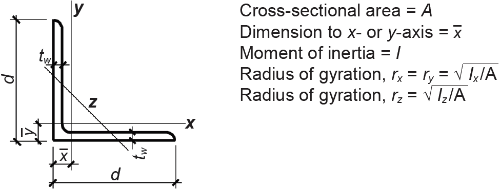
Table A-4.5: Dimensions and properties of selected steel L angles
| A. Angles with equal legs | ||||||
|---|---|---|---|---|---|---|
 | ||||||
| Designation | A (in2) | d (in.) | tw (in.) | x (in.) | Ix or Iy (in4) | Iz (in4) |
| L2 × 2 × ⅛1,2 | 0.491 | 2.00 | 0.1250 | 0.534 | 0.189 | 0.0751 |
| L2 × 2 × ¼ | 0.944 | 2.00 | 0.2500 | 0.586 | 0.346 | 0.141 |
| L2 × 2 × 5⁄16 | 1.16 | 2.00 | 0.3125 | 0.609 | 0.414 | 0.173 |
| L2 × 2 × ⅜ | 1.37 | 2.00 | 0.3750 | 0.632 | 0.476 | 0.203 |
| L3 × 3 × 3⁄161,2 | 1.09 | 3.00 | 0.1875 | 0.812 | 0.948 | 0.374 |
| L3 × 3 × ¼ | 1.44 | 3.00 | 0.2500 | 0.836 | 1.23 | 0.491 |
| L3 × 3 × ⅜ | 2.11 | 3.00 | 0.3750 | 0.884 | 1.75 | 0.712 |
| L3 × 3 × ½ | 2.76 | 3.00 | 0.5000 | 0.929 | 2.20 | 0.924 |
| L4 × 4 × ¼1,2 | 1.93 | 4.00 | 0.2500 | 1.08 | 3.00 | 1.18 |
| L4 × 4 × ⅜ | 2.86 | 4.00 | 0.3750 | 1.13 | 4.32 | 1.73 |
| L4 × 4 × ½ | 3.75 | 4.00 | 0.5000 | 1.18 | 5.52 | 2.25 |
| L4 × 4 × ¾ | 5.44 | 4.00 | 0.7500 | 1.27 | 7.62 | 3.25 |
| L5 × 5 × 5⁄161,2 | 3.07 | 5.00 | 0.3125 | 1.35 | 7.44 | 3.01 |
| L5 × 5 × 7⁄16 | 4.22 | 5.00 | 0.4375 | 1.40 | 10.0 | 4.08 |
| L5 × 5 × ⅝ | 5.90 | 5.00 | 0.6250 | 1.47 | 13.6 | 5.61 |
| L5 × 5 × ⅞ | 8.00 | 5.00 | 0.8750 | 1.56 | 17.8 | 7.56 |
| L6 × 6 × 5⁄161,2 | 3.67 | 6.00 | 0.3125 | 1.60 | 13.0 | 5.20 |
| L6 × 6 × ½ | 5.77 | 6.00 | 0.5000 | 1.67 | 19.9 | 8.04 |
| L6 × 6 × ¾ | 8.46 | 6.00 | 0.7500 | 1.77 | 28.1 | 11.6 |
| L6 × 6 × 1 | 11.0 | 6.00 | 1.0000 | 1.86 | 35.4 | 15.0 |
| L8 × 8 × ½1,2 | 7.84 | 8.00 | 0.5000 | 2.17 | 48.8 | 19.7 |
| L8 × 8 × ⅝ | 9.69 | 8.00 | 0.6250 | 2.21 | 59.6 | 24.2 |
| L8 × 8 × ⅞ | 13.3 | 8.00 | 0.8750 | 2.31 | 79.7 | 32.7 |
| L8 × 8 × 1⅛ | 16.8 | 8.00 | 1.1250 | 2.40 | 98.1 | 40.9 |
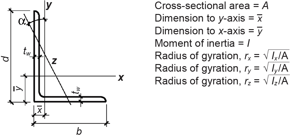
| B. Angles with unequal legs | ||||||||||
|---|---|---|---|---|---|---|---|---|---|---|
 | ||||||||||
| Designation | A (in2) |
d (in.) |
b (in.) |
tw (in.) |
x (in.) |
y (in.) |
Ix (in4) |
Iy (in4) |
Iz (in4) |
α (°) |
| L3 × 2 × ¼ | 1.20 | 3.00 | 2.00 | 0.2500 | 0.487 | 0.980 | 1.09 | 0.390 | 0.223 | 23.6 |
| L3 × 2 × 5⁄16 | 1.48 | 3.00 | 2.00 | 0.3125 | 0.511 | 1.01 | 1.32 | 0.467 | 0.271 | 23.4 |
| L3 × 2 × ⅜ | 1.75 | 3.00 | 2.00 | 0.3750 | 0.535 | 1.03 | 1.54 | 0.539 | 0.318 | 23.1 |
| L3 × 2 × ½ | 2.26 | 3.00 | 2.00 | 0.5000 | 0.580 | 1.08 | 1.92 | 0.667 | 0.409 | 22.4 |
| L3 × 2½ × ¼ | 1.32 | 3.00 | 2.50 | 0.2500 | 0.653 | 0.900 | 1.16 | 0.734 | 0.356 | 34.3 |
| L3 × 2½ × 5⁄16 | 1.63 | 3.00 | 2.50 | 0.3125 | 0.677 | 0.925 | 1.41 | 0.888 | 0.437 | 34.2 |
| L3 × 2½ × ⅜ | 1.93 | 3.00 | 2.50 | 0.3750 | 0.701 | 0.949 | 1.65 | 1.03 | 0.514 | 34.0 |
| L3 × 2½ × ½ | 2.50 | 3.00 | 2.50 | 0.5000 | 0.746 | 0.995 | 2.07 | 1.29 | 0.666 | 33.7 |
| L3½ × 2½ × ¼2 | 1.45 | 3.50 | 2.50 | 0.2500 | 0.607 | 1.10 | 1.81 | 0.775 | 0.425 | 26.7 |
| L3½ × 2½ × 5⁄16 | 1.79 | 3.50 | 2.50 | 0.3125 | 0.632 | 1.13 | 2.20 | 0.937 | 0.518 | 26.6 |
| L3½ × 2½ × ⅜ | 2.12 | 3.50 | 2.50 | 0.3750 | 0.655 | 1.15 | 2.56 | 1.09 | 0.608 | 26.3 |
| L3-½ × 2½ × ½ | 2.77 | 3.50 | 2.50 | 0.5000 | 0.701 | 1.20 | 3.24 | 1.36 | 0.782 | 25.9 |
| L4 × 3 × ¼1,2 | 1.69 | 4.00 | 3.00 | 0.2500 | 0.725 | 1.22 | 2.75 | 1.33 | 0.691 | 29.2 |
| L4 × 3 × ⅜ | 2.49 | 4.00 | 3.00 | 0.3750 | 0.775 | 1.27 | 3.94 | 1.89 | 1.01 | 28.9 |
| L4 × 3 × ½ | 3.25 | 4.00 | 3.00 | 0.5000 | 0.822 | 1.32 | 5.02 | 2.40 | 1.30 | 28.5 |
| L4 × 3 × ⅝ | 3.99 | 4.00 | 3.00 | 0.6250 | 0.867 | 1.37 | 6.01 | 2.85 | 1.59 | 28.1 |
| L4 × 3½ × ¼1,2 | 1.82 | 4.00 | 3.50 | 0.2500 | 0.897 | 1.14 | 2.89 | 2.07 | 0.950 | 37.2 |
| L4 × 3½ × 5⁄16 | 2.25 | 4.00 | 3.50 | 0.3125 | 0.923 | 1.17 | 3.53 | 2.52 | 1.17 | 37.1 |
| L4 × 3½ × ⅜ | 2.68 | 4.00 | 3.50 | 0.3750 | 0.947 | 1.20 | 4.15 | 2.96 | 1.38 | 37.1 |
| L4 × 3½ × ½ | 3.50 | 4.00 | 3.50 | 0.5000 | 0.994 | 1.24 | 5.30 | 3.76 | 1.808 | 36.9 |
| L5 × 3 × ¼1,2 | 1.94 | 5.00 | 3.00 | 0.2500 | 0.648 | 1.64 | 5.09 | 1.41 | 0.825 | 20.4 |
| L5 × 3 × 5⁄161,2 | 2.41 | 5.00 | 3.00 | 0.3125 | 0.673 | 1.67 | 6.24 | 1.72 | 1.01 | 20.2 |
| L5 × 3 × ⅜2 | 2.86 | 5.00 | 3.00 | 0.3750 | 0.698 | 1.69 | 7.35 | 2.01 | 1.20 | 20.0 |
| L5 × 3 × ½ | 3.75 | 5.00 | 3.00 | 0.5000 | 0.746 | 1.74 | 9.43 | 2.55 | 1.55 | 19.6 |
| L5 × 3½ × ¼1,2 | 2.07 | 5.00 | 3.50 | 0.2500 | 0.804 | 1.55 | 5.36 | 2.20 | 1.19 | 26.1 |
| L5 × 3½ × ⅜2 | 3.05 | 5.00 | 3.50 | 0.3750 | 0.854 | 1.60 | 7.75 | 3.15 | 1.74 | 25.9 |
| L5 × 3½ × ½ | 4.00 | 5.00 | 3.50 | 0.5000 | 0.901 | 1.65 | 9.96 | 4.02 | 2.25 | 25.6 |
| L5 × 3½ × ¾ | 5.85 | 5.00 | 3.50 | 0.7500 | 0.993 | 1.74 | 13.9 | 5.52 | 3.22 | 24.9 |
| L6 × 3½ × 5⁄161,2 | 2.89 | 6.00 | 3.50 | 0.3125 | 0.756 | 2.00 | 10.9 | 2.84 | 1.70 | 19.4 |
| L6 × 3½ × ⅜1,2 | 3.44 | 6.00 | 3.50 | 0.3750 | 0.781 | 2.02 | 12.9 | 3.33 | 2.00 | 19.2 |
| L6 × 3½ × ½ | 4.50 | 6.00 | 3.50 | 0.5000 | 0.829 | 2.07 | 16.6 | 4.24 | 2.58 | 18.9 |
| L6 × 4 × ⅜1,2 | 3.61 | 6.00 | 4.00 | 0.3750 | 0.933 | 1.93 | 13.4 | 4.86 | 2.73 | 24.0 |
| L6 × 4 × ½ | 4.75 | 6.00 | 4.00 | 0.5000 | 0.981 | 1.98 | 17.3 | 6.22 | 3.55 | 23.7 |
| L6 × 4 × ⅝ | 5.86 | 6.00 | 4.00 | 0.6250 | 1.03 | 2.03 | 21.0 | 7.48 | 4.32 | 23.5 |
| L6 × 4 × ⅞ | 8.00 | 6.00 | 4.00 | 0.8750 | 1.12 | 2.12 | 27.7 | 9.70 | 5.82 | 22.8 |
| L7 × 4 × ⅜1,2 | 4.00 | 7.00 | 4.00 | 0.3750 | 0.861 | 2.35 | 20.5 | 5.06 | 3.05 | 18.7 |
| L7 × 4 × ½2 | 5.26 | 7.00 | 4.00 | 0.5000 | 0.910 | 2.40 | 26.6 | 6.48 | 3.95 | 18.5 |
| L7 × 4 × ⅝ | 6.50 | 7.00 | 4.00 | 0.6250 | 0.958 | 2.45 | 32.4 | 7.79 | 4.80 | 18.2 |
| L7 × 4 × ¾ | 7.74 | 7.00 | 4.00 | 0.7500 | 1.00 | 2.50 | 37.8 | 9.00 | 5.64 | 18.0 |
| L8 × 4 × ½1,2 | 5.80 | 8.00 | 4.00 | 0.5000 | 0.854 | 2.84 | 38.6 | 6.75 | 4.32 | 14.9 |
| L8 × 4 × ⅝ | 7.16 | 8.00 | 4.00 | 0.6250 | 0.902 | 2.89 | 47.0 | 8.11 | 5.24 | 14.7 |
| L8 × 4 × ¾ | 8.49 | 8.00 | 4.00 | 0.7500 | 0.949 | 2.94 | 55.0 | 9.37 | 6.13 | 14.4 |
| L8 × 4 × 1 | 11.1 | 8.00 | 4.00 | 1.0000 | 1.04 | 3.03 | 69.7 | 11.6 | 7.87 | 13.9 |
| L8 × 6 × ½1,2 | 6.80 | 8.00 | 6.00 | 0.5000 | 1.46 | 2.46 | 44.4 | 21.7 | 11.5 | 29.1 |
| L8 × 6 × ⅝ | 8.41 | 8.00 | 6.00 | 0.6250 | 1.51 | 2.50 | 54.2 | 26.4 | 14.1 | 29.0 |
| L8 × 6 × ⅞ | 11.5 | 8.00 | 6.00 | 0.8750 | 1.60 | 2.60 | 72.4 | 34.9 | 18.9 | 28.6 |
| L8 × 6 × 1 | 13.1 | 8.00 | 6.00 | 1.0000 | 1.65 | 2.65 | 80.9 | 38.8 | 21.3 | 28.5 |
Notes:
1. Section not compact for steel with Fy = 36 ksi.
2. Section slender for steel with Fy = 36 ksi.
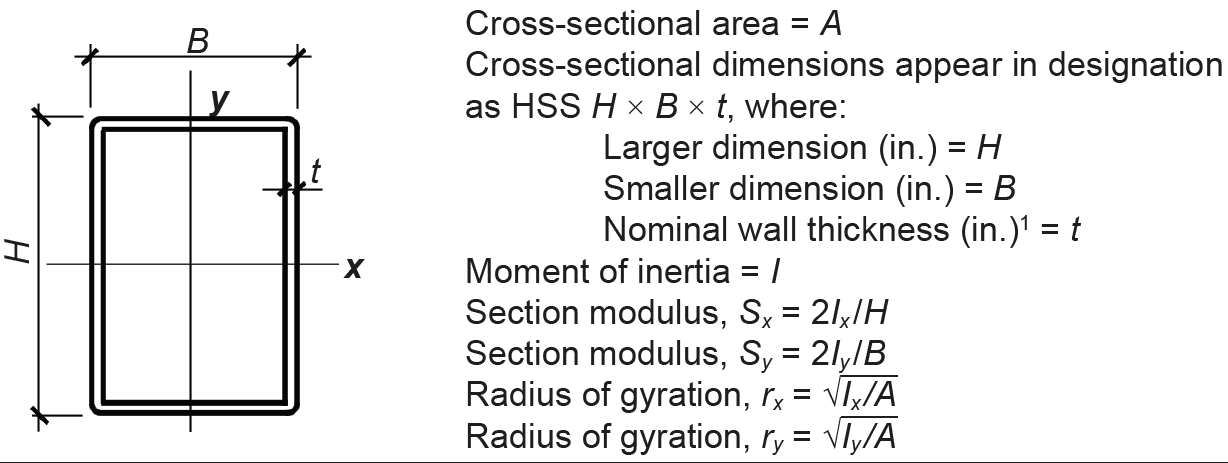
Table A-4.6: Dimensions and properties of selected steel rectangular and square hollow structural sections (HSS)
 | |||||||
| Designation | A (in2) | Design wall thickness, t (in.)1 | Sx (in3) | Zx (in3) | Ix (in4) | Iy (in4) | ry (in.) |
|---|---|---|---|---|---|---|---|
| HSS2 × 2 × 3/16 HSS2 × 2 × 1/4 |
1.19 1.51 |
0.174 0.233 |
0.641 0.747 |
0.797 0.964 |
0.641 0.747 |
0.641 0.747 |
0.733 0.704 |
| HSS2½ × 2½ × 3/16 HSS2½ × 2½ × 5/16 |
1.54 2.35 |
1.54 2.35 |
1.08 1.46 |
1.32 1.88 |
1.35 1.82 |
1.35 1.82 |
0.937 0.880 |
| HSS3 × 3 × 3/16 HSS3 × 3 × 3/8 |
1.89 3.39 |
0.174 0.349 |
1.64 2.52 |
1.97 3.25 |
2.46 3.78 |
2.46 3.78 |
1.14 1.06 |
| HSS3½ × 3½ × 3/16 HSS3½ × 3½ × 3/8 |
2.24 4.09 |
0.174 0.349 |
2.31 3.71 |
2.76 4.69 |
4.05 6.49 |
4.05 6.49 |
1.35 1.26 |
| HSS4 × 3 × 3/16 HSS4 × 3 × 3/8 |
2.24 4.09 |
0.174 0.349 |
2.47 3.97 |
3.00 5.12 |
4.93 7.93 |
3.16 5.01 |
1.19 1.11 |
| HSS4 × 4 × 1/4 HSS4 × 4 × 1/2 |
3.37 6.02 |
0.233 0.465 |
3.90 5.97 |
4.69 7.70 |
7.80 11.9 |
7.80 11.9 |
1.52 1.41 |
| HSS6 × 4 × 1/4 HSS6 × 4 × 1/2 |
4.30 7.88 |
0.233 0.465 |
6.96 11.3 |
8.53 14.6 |
20.9 34.0 |
11.1 17.8 |
1.61 1.50 |
| HSS6 × 6 × 1/4 HSS6 × 6 × 5/8 |
5.24 11.7 |
0.233 0.581 |
9.54 18.4 |
11.2 23.2 |
28.6 55.2 |
28.6 55.2 |
2.34 2.17 |
| HSS8 × 4 × 1/4 HSS8 × 4 × 5/8 |
5.24 11.7 |
0.233 0.581 |
10.6 20.5 |
13.3 27.4 |
42.5 82.0 |
14.4 26.6 |
1.66 1.51 |
| HSS8 × 8 × 1/42 HSS8 × 8 × 5/8 |
7.10 16.4 |
0.233 0.581 |
17.7 36.5 |
20.5 44.7 |
70.7 146 |
70.7 146 |
3.15 2.99 |
| HSS12 × 4 × 1/4 HSS12 × 4 × 5/8 |
7.10 16.4 |
0.233 0.581 |
19.9 40.8 |
25.6 55.5 |
119 245 |
21.0 40.4 |
1.72 1.57 |
| HSS12 × 8 × 1/42 HSS12 × 8 × 5/8 |
8.96 21.0 |
0.233 0.581 |
30.6 66.1 |
36.6 82.1 |
184 397 |
98.8 210 |
3.32 3.16 |
| HSS12 × 12 × 1/42 HSS12 × 12 × 5/8 |
10.8 25.7 |
0.233 0.581 |
41.4 91.4 |
47.6 109 |
248 548 |
248 548 |
4.79 4.62 |
| HSS16 × 4 × 5/16 HSS16 × 4 × 5/8 |
11.1 21.0 |
0.291 0.581 |
38.5 67.3 |
51.1 92.9 |
308 539 |
33.2 54.1 |
1.73 1.60 |
| HSS16 × 8 × 5/16 HSS16 × 8 × 5/8 |
13.4 25.7 |
0.291 0.581 |
56.4 102 |
69.4 129 |
451 815 |
155 274 |
3.40 3.27 |
| HSS16 × 12 × 5/162 HSS16 × 12 × 5/8 |
15.7 30.3 |
0.291 0.581 |
74.4 136 |
87.7 165 |
595 1090 |
384 700 |
4.94 4.80 |
| HSS16 × 16 × 3/8 HSS16 × 16 × 5/8 |
21.5 35.0 |
0.349 0.581 |
109 171 |
126 200 |
873 1370 |
873 1370 |
6.37 6.25 |
| HSS20 × 4 × 3/8 HSS20 × 4 × 1/2 |
16.0 20.9 |
0.349 0.465 |
65.7 83.8 |
89.3 115 |
657 838 |
47.6 58.7 |
1.73 1.68 |
| HSS20 × 8 × 3/8 HSS20 × 8 × 5/8 |
18.7 30.3 |
0.349 0.581 |
92.6 144 |
117 185 |
926 1440 |
222 338 |
3.44 3.34 |
| HSS20 × 12 × 3/82 HSS20 × 12 × 5/8 |
21.5 35.0 |
0.349 0.581 |
120 188 |
144 230 |
1200 1880 |
547 851 |
5.04 4.93 |
Notes:
1. The nominal wall thickness, t, in the designation for an HSS shape (for example, ½ in. or ¼ in.) is different from the "design wall thickness," t, which is tabulated for each section and which is permitted to be smaller than the nominal value.
2. Section is not compact, based on flange slenderness: use reduced nominal bending strength, Mn, as follows:
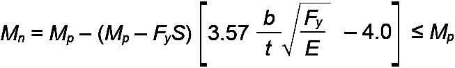
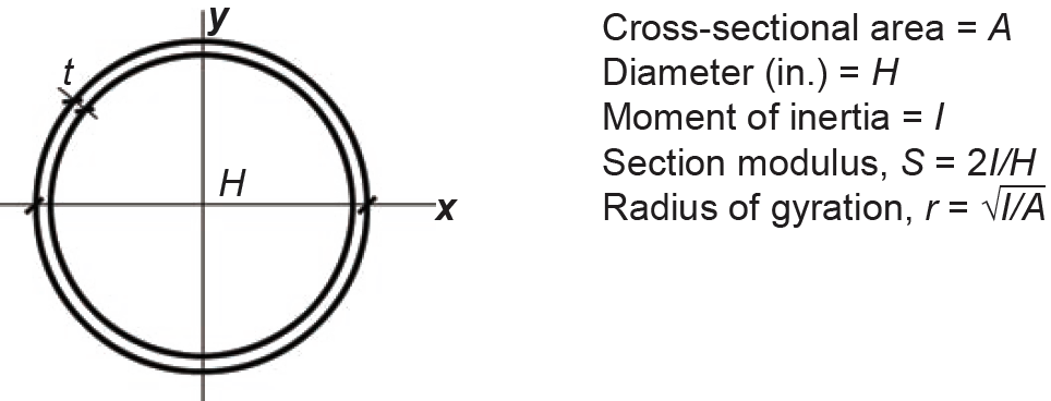
Table A-4.7: Dimensions and properties of selected steel round hollow structural sections (HSS)
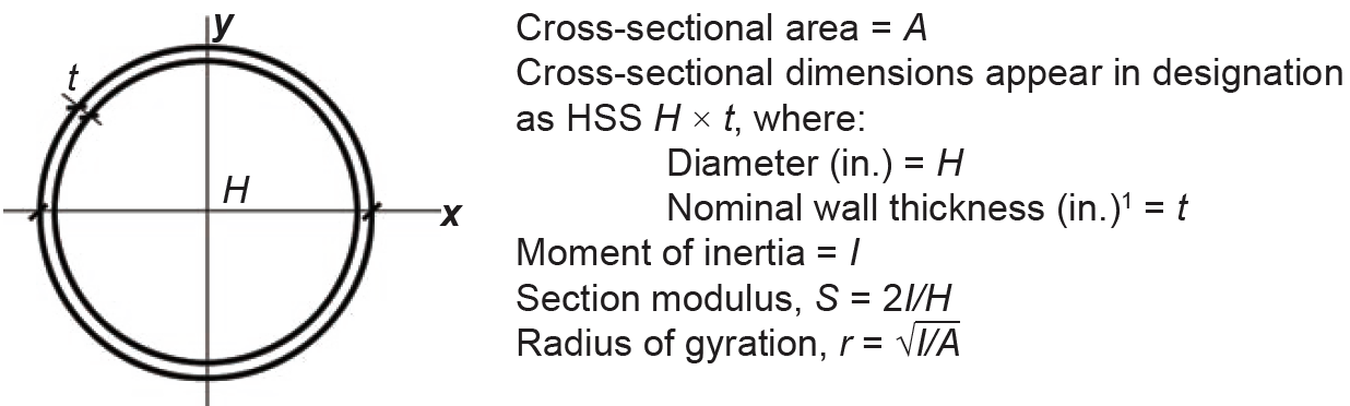 | |||||
| Designation | A (in2) | Design wall thickness, t (in.)1 | I (in4) | r (in.) | |
|---|---|---|---|---|---|
| HSS1.660 × 0.140 | 0.625 | 0.130 | 0.184 | 0.543 | |
| HSS1.990 × 0.120 HSS1.990 × 0.188 |
0.624 0.943 |
0.111 0.174 |
0.251 0.355 |
0.634 0.613 | |
| HSS2.375 × 0.125 HSS2.375 × 0.250 |
0.823 1.57 |
0.116 0.233 |
0.527 0.910 |
0.800 0.762 | |
| HSS2.500 × 0.125 HSS2.500 × 0.250 |
0.869 1.66 |
0.116 0.233 |
0.619 1.08 |
0.844 0.806 | |
| HSS3.000 × 0.125 HSS3.000 × 0.250 |
1.05 2.03 |
0.116 0.233 |
1.09 1.95 |
1.02 0.982 | |
| HSS3.500 × 0.125 HSS3.500 × 0.313 |
1.23 2.93 |
0.116 0.291 |
1.77 3.81 |
1.20 1.14 | |
| HSS4.000 × 0.125 HSS4.000 × 0.313 |
1.42 3.39 |
0.116 0.291 |
2.67 5.87 |
1.37 1.32 | |
| HSS6.000 × 0.250 HSS6.000 × 0.500 |
4.22 8.09 |
0.233 0.465 |
17.6 31.2 |
2.04 1.96 | |
| HSS8.625 × 0.250 HSS8.625 × 0.625 |
6.14 14.7 |
0.233 0.581 |
54.1 119 |
2.97 2.85 | |
| HSS10.000 × 0.250 HSS10.000 × 0.625 |
7.15 17.2 |
0.233 0.581 |
85.3 191 |
3.45 3.34 | |
| HSS12.750 × 0.375 HSS12.750 × 0.500 |
13.6 17.9 |
0.349 0.465 |
262 339 |
4.39 4.35 | |
| HSS14.000 × 0.375 HSS14.000 × 0.625 |
15.0 24.5 |
0.349 0.581 |
349 552 |
4.83 4.75 | |
| HSS16.000 × 0.375 HSS16.000 × 0.625 |
17.2 28.1 |
0.349 0.581 |
526 838 |
5.53 5.46 | |
| HSS18.000 × 0.500 | 25.6 | 0.465 | 985 | 6.20 | |
| HSS20.000 × 0.500 | 28.5 | 0.465 | 1360 | 6.91 | |
Note:
1. The nominal wall thickness, t, in the designation for an HSS shape (e.g., 0.500 in. or 0.250 in.) is different from the "design wall thickness," t, which is tabulated for each section and which is permitted to be smaller than the nominal value.
Table A-4.8: Dimensions and properties of selected steel pipe
 | |||||
| Designation | A (in2) | Design wall thickness, t (in.)1 | Diameter (in.) | I (in4) | r (in.) |
|---|---|---|---|---|---|
| Standard weight steel pipe | |||||
| Pipe 2 Std. | 1.02 | 0.143 | 2.38 | 0.627 | 0.791 |
| Pipe 2½ Std. | 1.61 | 0.189 | 2.88 | 1.45 | 0.952 |
| Pipe 3 Std. | 2.07 | 0.201 | 3.50 | 2.85 | 1.17 |
| Pipe 3½ Std. | 2.50 | 0.211 | 4.00 | 4.52 | 1.34 |
| Pipe 4 Std. | 2.96 | 0.221 | 4.50 | 6.82 | 1.51 |
| Pipe 5 Std. | 4.01 | 0.241 | 5.56 | 14.3 | 1.88 |
| Pipe 6 Std. | 5.20 | 0.261 | 6.63 | 26.5 | 2.25 |
| Pipe 8 Std. | 7.85 | 0.300 | 8.63 | 68.1 | 2.95 |
| Pipe 10 Std. | 11.5 | 0.340 | 10.8 | 151 | 3.68 |
| Pipe 12 Std. | 13.7 | 0.349 | 12.8 | 262 | 4.39 | Extra strong steel pipe |
| Pipe 2 x-Strong | 1.40 | 0.204 | 2.38 | 0.827 | 0.771 |
| Pipe 2½ x-Strong | 2.10 | 0.257 | 2.88 | 1.83 | 0.930 |
| Pipe 3 x-Strong | 2.83 | 0.280 | 3.50 | 3.70 | 1.14 |
| Pipe 3½ x-Strong | 3.43 | 0.296 | 4.00 | 5.94 | 1.31 |
| Pipe 4 x-Strong | 4.14 | 0.315 | 4.50 | 9.12 | 1.48 |
| Pipe 5 x-Strong | 5.73 | 0.349 | 5.56 | 19.5 | 1.85 |
| Pipe 6 x-Strong | 7.83 | 0.403 | 6.63 | 38.3 | 2.20 |
| Pipe 8 x-Strong | 11.9 | 0.465 | 8.63 | 100 | 2.89 |
| Pipe 10 x-Strong | 15.1 | 0.465 | 10.8 | 199 | 3.64 |
| Pipe 12 x-Strong | 17.5 | 0.465 | 12.8 | 339 | 4.35 | Double-extra strong steel pipe |
| Pipe 2 xx-Strong | 2.51 | 0.406 | 2.38 | 1.27 | 0.711 |
| Pipe 2½ xx-Strong | 3.83 | 0.514 | 2.88 | 2.78 | 0.854 |
| Pipe 3 xx-Strong | 5.17 | 0.559 | 3.50 | 5.79 | 1.06 |
| Pipe 4 xx-Strong | 7.66 | 0.628 | 4.50 | 14.7 | 1.39 |
| Pipe 5 xx-Strong | 10.7 | 0.699 | 5.56 | 32.2 | 1.74 |
| Pipe 6 xx-Strong | 14.7 | 0.805 | 6.63 | 63.5 | 2.08 |
| Pipe 8 xx-Strong | 20.0 | 0.816 | 8.63 | 154 | 2.78 |
Table A-4.9: Shear lag coefficient, U, for bolted and welded steel connections in tension1
| Condition | Shear lag coefficient, U | Diagram |
|---|---|---|
| All parts of the element (e.g., web, flanges, legs) are connected by bolts or welds. | U = 1.0 |  |
| Transverse welds connecting some, but not all, of the cross-sectional "parts." | U = 1.0, but the net area, An, is taken as only that portion of the element cross section (consisting of flanges, webs, legs, and so on) that is directly connected by the transverse welds. | 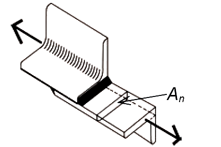 |
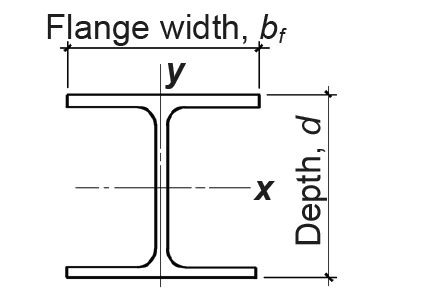
| Longitudinal welds connecting steel plates or other shapes. | 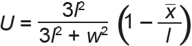 where l = (l1 + l2)/2 and l1 and l2 are at least 4 times the weld size; and x is the distance measured from the connection plane to the centroid of the member. |
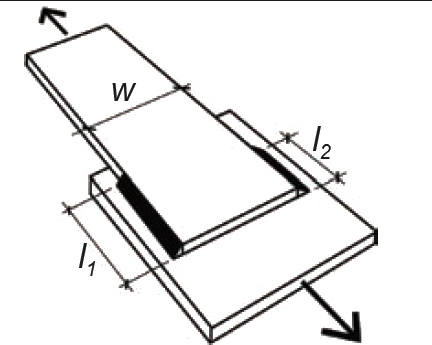 |
| Bolts connecting wide-flange (W) shapes; or M, S, HP shapes; or Tees made from any of those sections. | U = 0.90 where bf ≥ 0.67d and flange is connected with at least 3 bolts per line. U = 0.85 where bf < 0.67d and flange is connected with at least 3 bolts per line. U = 0.70 where only the web is connected with at least 4 bolts per line. |
 |
| Bolts connecting single and double angles (L). | U = 0.80 where one leg of the angle is connected with at least 4 bolts per line. U = 0.60 where one leg of the angle is connected with 3 bolts per line. (See note 1 for angles connected with less than 3 bolts per line.) |
 |
Note:
1. The shear lag coefficient, U, for all tension members except plates and HSS, can be taken as U = 1 – x /l, where x is the distance measured from the connection plane to the centroid of the member and U is the length of the connection, measured either along the weld or measured from the first to the last bolt, in either case parallel to the direction of the tension force. For wide-flange shapes bolted through the flanges, the centroid is taken for half of the cross section, i.e., for the "tee" (WT shape), rather than for the whole W shape. Alternatively, the values for U listed in this table can be used in lieu of this equation.
Table A-4.10: Allowable axial loads1,2,3 (kips), A992 steel wide-flange columns (Fy = 50 ksi)
| Designa- tion | Effective length, KL (ft) | |||||||||||||||
|---|---|---|---|---|---|---|---|---|---|---|---|---|---|---|---|---|
| 10 | 12 | 14 | 16 | 18 | 20 | 22 | 24 | 26 | 28 | 30 | 32 | 34 | 36 | 38 | 40 | |
| W4 × 13 | 39 | 27 | 20 | 15 | 12 | 9 | 8 | 6 | 5 | 5 | 4 | 3 | 3 | 3 | 2 | 2 |
| W5 × 16 W5 × 19 |
72 87 |
54 65 |
39 48 |
30 37 |
24 29 |
19 23 |
16
19 |
13
16 |
11
14 |
9
12 |
8
10 |
7
9 |
6
8 |
6
7 |
5
6 |
4
5 |
| W6 × 9 W6 × 12 W6 × 16 W6 × 15 W6 × 20 W6 × 25 |
22 31 46 80 110 139 |
15 21 32 64 89 114 |
11 15 23 49 70 89 |
8
12
1837 53 69 |
7
9
14
2942 54 |
5
7
11
2434 44 |
4
6
9
2028 36 |
3
5
8
1623 30 |
3
4
6
1420 26 |
2
3
5
12
17
22 |
2
3
5
10
15
19 |
2
3
4
9
13
17 |
1
2
4
8
11
15 |
1
2
3
7
10
13 |
1
2
3
6
9
12 |
1
1
2
6
8
11 |
| W8 × 13 W8 × 15 W8 × 18 W8 × 21 W8 × 24 W8 × 28 W8 × 31 W8 × 35 W8 × 40 W8 × 48 W8 × 58 W8 × 67 |
28 35 78 95 141 165 211 238 271 330 403 466 |
19 24 57 70 118 138 188 213 243 297 363 420 |
14 18 42 52 95 112 164 186 213 262 320 372 |
11
13
3239 74 88 141 160 183 226 277 323 |
8
10
2531 59 69 118 134 154 191 236 276 |
7
8
2025 47 56 97 110 127 159 196 230 |
5
7
17
21
3946 80 91 104 131 162 190 |
4
6
14
17
3339 67 76 88 110 136 160 |
4
5
12
15
2833 57 65 75 94 116 136 |
3
4
10
13
24
28
4956 64 81 100 117 |
3
3
9
11
21
25
4349 56 70 87 102 |
2
3
8
9
18
22
3743 49 62 76 90 |
2
3
7
8
16
19
33
38
4355 68 79 |
2
2
6
7
14
17
29
34
39
49
60
71 |
1
2
5
7
13
15
26
30
35
44
54
63 |
1
2
5
6
11
14
24
27
31
39
49
57 |
| W10 × 15 W10 × 19 W10 × 26 W10 × 30 W10 × 33 W10 × 39 W10 × 45 W10 × 49 W10 × 54 W10 × 60 W10 × 68 W10 × 77 W10 × 88 W10 × 100 W10 × 112 |
30 44 128 151 219 263 306 366 402 451 509 581 668 755 850 |
20 31 100 118 194 233 273 340 375 421 475 543 625 706 797 |
15
2274 88 168 203 238 313 345 387 438 500 577 653 739 |
11
17
5767 142 173 204 283 313 352 398 456 527 597 676 |
9
13
4553 117 144 171 254 281 316 358 410 475 539 612 |
7
11
3643 95 117 140 224 248 280 318 364 423 481 548 |
6
9
3035 78 97 115 195 217 244 278 319 372 424 484 |
5
7
25
30
6681 97 168 187 211 241 277 323 369 423 |
4
6
21
25
5669 82 143 159 180 206 236 277 317 364 |
3
5
18
22
4860 71 123 137 155 177 204 239 273 314 |
3
4
16
19
4252 62 107 120 135 154 177 208 238 273 |
2
4
14
16
3745 54 94 105 119 136 156 183 209 240 |
2
3
12
14
32
40
48
8393 105 120 138 162 185 213 |
2
3
11
13
29
36
43
7483 94< 107 123 144 165 190 |
2
3
10
11
26
32
38
6774 84 96 110 129 148 170 |
1
2
9
10
23
29
35
6067 76 87 100 117 134 154 |
| Designa- tion | Effective length, KL (ft) | |||||||||||||||
| 10 | 12 | 14 | 16 | 18 | 20 | 22 | 24 | 26 | 28 | 30 | 32 | 34 | 36 | 38 | 40 | |
| W12 × 40 W12 × 45 W12 × 50 W12 × 53 W12 × 58 W12 × 65 W12 × 72 W12 × 79 W12 × 87 W12 × 96 W12 × 106 W12 × 120 W12 × 136 W12 × 152 W12 × 170 W12 × 190 W12 × 210 W12 × 230 W12 × 252 W12 × 279 W12 × 305 W12 × 336 |
264 297 332 393 430 509 563 620 685 756 837 946 1075 1206 1352 1517 1677 1841 2018 2236 2448 2713 |
234 263 294 365 400 484 536 590 652 720 798 902 1026 1153 1293 1452 1607 1764 1936 2147 2353 2610 |
202 227 255 333 366 456 505 556 615 680 754 853 971 1092 1226 1379 1527 1678 1843 2046 2246 2494 |
171 193 216 301 331 425 471 519 575 636 706 800 912 1026 1154 1299 1440 1584 1742 1936 2128 2367 |
141 159 179 268 296 393 436 481 533 590 656 743 848 957 1077 1213 1347 1484 1634 1819 2001 2230 |
114 129 146 235 260 360 400 441 490 543 604 685 783 884 997 1125 1250 1380 1520 1696 1869 2087 |
94 107 120 203 226 327 363 401 446 495 551 626 717 811 915 1034 1152 1273 1405 1569 1733 1939 |
79 90 101 173 194 294 327 361 402 447 498 567 650 737 834 944 1052 1165 1288 1442 1595 1789 |
67 76 86 148 165 262 292 323 360 400 447 509 585 664 753 854 954 1058 1172 1315 1458 1639 |
58 66 74 127 142 231 258 286 319 355 397 453 522 594 675 767 859 954 1058 1190 1323 1491 |
51 57 65 111 124 201 226 250 279 312 349 399 461 527 600 683 766 853 948 1069 1191 1347 |
44 50 57 97 109 177 198 219 245 274 307 351 406 463 528 602 677 755 842 953 1065 1209 |
39
44
50
8696 157 176 194 217 243 272 311 359 410 467 533 600 669 746 844 944 1074 |
35
40
45
7786 140 157 173 194 216 242 277 320 366 417 476 535 597 665 753 842 958 |
31
35
40
6977 125 140 155 174 194 218 249 287 328 374 427 480 536 597 676 756 860 |
28
32
36
6269 113 127 140 157 175 196 224 259 296 338 385 433 483 539 610 682 776 |
| Designa- tion | Effective length, KL (ft) | |||||||||||||||
| 10 | 12 | 14 | 16 | 18 | 20 | 22 | 24 | 26 | 28 | 30 | 32 | 34 | 36 | 38 | 40 | |
| W14 × 433 W14 × 48 W14 × 53 W14 × 61 W14 × 68 W14 × 74 W14 × 82 W14 × 90 W14 × 99 W14 × 109 W14 × 120 W14 × 132 W14 × 145 W14 × 159 W14 × 176 W14 × 193 W14 × 211 W14 × 233 W14 × 257 W14 × 283 W14 × 311 W14 × 342 W14 × 370 W14 × 398 W14 × 426 W14 × 455 W14 × 500 W14 × 550 W14 × 605 W14 × 665 W14 × 730 W14 × 808 W14 × 873 |
281 316 351 449 503 550 605 734 807 888 980 1078 1196 1309 1453 1594 1741 1926 2127 2347 2577 2851 3080 3309 3539 3797 4171 4603 5065 5585 6136 6811 7364 |
247 278 309 416 466 510 561 710 780 859 948 1043 1161 1271 1412 1550 1693 1874 2070 2285 2511 2779 3003 3228 3453 3707 4073 4498 4952 5465 6008 6677 7223 |
212 239 266 380 425 466 513 682 749 826 911 1003 1122 1229 1364 1499 1638 1813 2005 2214 2434 2696 2914 3134 3354 3602 3961 4378 4823 5327 5860 6522 7060 |
177 201 224 342 383 421 463 651 716 789 871 960 1078 1181 1312 1442 1577 1747 1932 2135 2348 2602 2814 3029 3243 3486 3836 4243 4678 5172 5694 6348 6877 |
145 165 185 303 340 374 412 618 680 749 828 912 1030 1129 1255 1381 1510 1674 1853 2049 2255 2501 2706 2915 3122 3358 3698 4095 4519 5001 5512 6156 6675 |
117 134 150 265 298 329 362 583 641 707 782 862 979 1074 1195 1315 1439 1596 1768 1957 2155 2392 2590 2792 2992 3221 3551 3935 4348 4817 5315 5948 6456 |
97 110 123 229 257 285 313 546 601 664 734 810 926 1016 1131 1246 1364 1514 1678 1860 2049 2277 2467 2662 2855 3076 3394 3766 4166 4621 5105 5727 6223 |
82 93 104 194 219 242 267 509 560 619 685 756 871 957 1065 1174 1287 1429 1586 1759 1940 2158 2340 2527 2712 2924 3231 3590 3976 4416 4885 5494 5977 |
70 79 88 165 186 206 227 471 519 574 635 702 815 896 998 1101 1207 1342 1491 1656 1827 2035 2208 2388 2564 2768 3062 3407 3778 4204 4657 5252 5720 |
60 68 76 143 161 178 196 434 478 529 585 647 759 834 930 1028 1127 1255 1395 1551 1713 1910 2075 2246 2414 2609 2889 3220 3576 3986 4422 5002 5456 |
52 59 66 124 140 155 171 397 437 484 536 594 702 773 862 954 1047 1167 1298 1446 1599 1785 1940 2103 2262 2448 2715 3031 3371 3764 4184 4747 5185 |
—
52
58109 123 136 150 360 398 441 488 541 647 712 795 881 968 1079 1202 1341 1485 1660 1806 1960 2111 2287 2540 2841 3165 3541 3942 4488 4910 |
—
46
51
96109 121 133 326 359 399 442 491 592 653 730 809 890 994 1108 1238 1372 1536 1674 1819 1961 2127 2367 2651 2960 3317 3701 4229 4634 |
—
41
46
8697 107 118 292 322 358 397 441 540 595 666 740 814 910 1017 1137 1262 1415 1544 1680 1813 1969 2195 2464 2756 3096 3461 3970 4358 |
—
37
41
7787 96 106 262 289 321 356 396 488 539 604 673 741 830 928 1040 1155 1298 1417 1545 1669 1816 2028 2281 2557 2878 3224 3713 4084 |
—
33
37
7078 87 96 236 261 290 322 357 441 487 545 607 669 750 841 944 1051 1184 1295 1414 1530 1667 1865 2103 2361 2665 2992 3461 3814 |
Notes:
1. Slenderness ratio, KL/r > 200, for table cells shown with light tone: such slender columns are permitted but not recommended.
2. Interpolation can be used to find approximate values for allowable axial loads for effective lengths not shown in the table (i.e., for odd numbers between 10 ft and 40 ft).
3. Section is "slender" for compression; values have been appropriately lowered.
Table A-4.11: Allowable stresses for A992 steel columns (Fy = 50 ksi)
KL/r Fc |
KL/r Fc |
KL/r Fc |
KL/r Fc |
KL/r Fc |
|---|---|---|---|---|
1 29.9 | 41 26.5 | 81 18.5 | 121 10.3 | 161 5.80 |
2 29.9 | 42 26.3 | 82 18.3 | 122 10.1 | 162 5.73 |
3 29.9 | 43 26.2 | 83 18.1 | 123 9.93 | 163 5.66 |
4 29.9 | 44 26.0 | 84 17.9 | 124 9.77 | 164 5.59 |
5 29.9 | 45 25.8 | 85 17.7 | 125 9.62 | 165 5.52 |
6 29.9 | 46 25.6 | 86 17.4 | 126 9.46 | 166 5.45 |
7 29.8 | 47 25.5 | 87 17.2 | 127 9.32 | 167 5.39 |
8 29.8 | 48 25.3 | 88 17.0 | 128 9.17 | 168 5.32 |
9 29.8 | 49 25.1 | 89 16.8 | 129 9.03 | 169 5.26 |
10 29.7 | 50 24.9 | 90 16.6 | 130 8.89 | 170 5.20 |
11 29.7 | 51 24.8 | 91 16.3 | 131 8.76 | 171 5.14 |
12 29.6 | 52 24.6 | 92 16.1 | 132 8.62 | 172 5.08 |
13 29.6 | 53 24.4 | 93 15.9 | 133 8.49 | 173 5.02 |
14 29.5 | 54 24.2 | 94 15.7 | 134 8.37 | 174 4.96 |
15 29.5 | 55 24.0 | 95 15.5 | 135 8.24 | 175 4.91 |
16 29.4 | 56 23.8 | 96 15.3 | 136 8.12 | 176 4.85 |
17 29.3 | 57 23.6 | 97 15.0 | 137 8.01 | 177 4.80 |
18 29.2 | 58 23.4 | 98 14.8 | 138 7.89 | 178 4.74 |
19 29.2 | 59 23.2 | 99 14.6 | 139 7.78 | 179 4.69 |
20 29.1 | 60 23.0 | 100 14.4 | 140 7.67 | 180 4.64 |
21 29.0 | 61 22.8 | 101 14.2 | 141 7.56 | 181 4.59 |
22 28.9 | 62 22.6 | 102 14.0 | 142 7.45 | 182 4.54 |
23 28.8 | 63 22.4 | 103 13.8 | 143 7.35 | 183 4.49 |
24 28.7 | 64 22.2 | 104 13.6 | 144 7.25 | 184 4.44 |
25 28.6 | 65 22.0 | 105 13.4 | 145 7.15 | 185 4.39 |
26 28.5 | 66 21.8 | 106 13.2 | 146 7.05 | 186 4.34 |
27 28.4 | 67 21.6 | 107 13.0 | 147 6.95 | 186 4.34 |
28 28.3 | 68 21.4 | 108 12.8 | 148 6.86 | 188 4.25 |
29 28.2 | 69 21.1 | 109 12.6 | 149 6.77 | 189 4.21 |
30 28.0 | 70 20.9 | 110 12.4 | 150 6.68 | 190 4.16 |
31 27.9 | 71 20.7 | 111 12.2 | 151 6.59 | 191 4.12 |
32 27.8 | 72 20.5 | 112 12.0 | 152 6.50 | 192 4.08 |
33 27.6 | 73 20.3 | 113 11.8 | 153 6.42 | 193 4.03 |
34 27.5 | 74 20.1 | 114 11.6 | 154 6.34 | 194 3.99 |
35 27.4 | 75 19.8 | 115 11.4 | 155 6.25 | 195 3.95 |
36 27.2 | 76 19.6 | 116 11.2 | 156 6.17 | 196 3.91 |
37 27.1 | 77 19.4 | 117 11.0 | 157 6.10 | 197 3.87 |
38 26.9 | 78 19.2 | 118 10.8 | 158 6.02 | 198 3.83 |
39 26.8 | 79 19.0 | 119 10.6 | 159 5.94 | 199 3.79 |
40 26.6 | 80 18.8 | 120 10.4 | 160 5.87 | 200 3.76 |
Table A-4.12: Allowable stresses for A500 Grade B HSS rectangular columns (Fy = 46 ksi)
KL/r Fc |
KL/r Fc |
KL/r Fc |
KL/r Fc |
KL/r Fc |
|---|---|---|---|---|
1 27.5 | 41 24.6 | 81 17.7 | 121 10.3 | 161 5.80 |
2 27.5 | 42 24.5 | 82 17.5 | 122 10.1 | 162 5.73 |
3 27.5 | 43 24.3 | 83 17.3 | 123 9.93 | 163 5.66 |
4 27.5 | 44 24.2 | 84 17.1 | 124 9.77 | 164 5.59 |
5 27.5 | 45 24.0 | 85 16.9 | 125 9.62 | 165 5.52 |
6 27.5 | 46 23.9 | 86 16.7 | 126 9.46 | 166 5.45 |
7 27.5 | 47 23.7 | 87 16.6 | 127 9.32 | 167 5.39 |
8 27.4 | 48 23.6 | 88 16.4 | 128 9.17 | 168 5.32 |
9 27.4 | 49 23.4 | 89 16.2 | 129 9.03 | 169 5.26 |
10 27.4 | 50 23.3 | 90 16.0 | 130 8.89 | 170 5.20 |
11 27.3 | 51 23.1 | 91 15.8 | 131 8.76 | 171 5.14 |
12 27.3 | 52 23.0 | 92 15.6 | 132 8.62 | 172 5.08 |
13 27.2 | 53 22.8 | 93 15.4 | 133 8.49 | 173 5.02 |
14 27.2 | 54 22.6 | 94 15.2 | 134 8.37 | 174 4.96 |
15 27.1 | 55 22.5 | 95 15.0 | 135 8.24 | 175 4.91 |
16 27.1 | 56 22.3 | 96 14.8 | 136 8.12 | 176 4.85 |
17 27.0 | 57 22.1 | 97 14.6 | 137 8.01 | 177 4.80 |
18 27.0 | 58 22.0 | 98 14.4 | 138 7.89 | 178 4.74 |
19 26.9 | 59 21.8 | 99 14.2 | 139 7.78 | 179 4.69 |
20 26.8 | 60 21.6 | 100 14.1 | 140 7.67 | 180 4.64 |
21 26.7 | 61 21.4 | 101 13.9 | 141 7.56 | 181 4.59 |
22 26.7 | 62 21.3 | 102 13.7 | 142 7.45 | 182 4.54 |
23 26.6 | 63 21.1 | 103 13.5 | 143 7.35 | 183 4.49 |
24 26.5 | 64 20.9 | 104 13.3 | 144 7.25 | 184 4.44 |
25 26.4 | 65 20.7 | 105 13.1 | 145 7.15 | 185 4.39 |
26 26.3 | 66 20.5 | 106 12.9 | 146 7.05 | 186 4.34 |
27 26.2 | 67 20.4 | 107 12.8 | 147 6.95 | 186 4.34 |
28 26.1 | 68 20.2 | 108 12.6 | 148 6.86 | 188 4.25 |
29 26.0 | 69 20.0 | 109 12.4 | 149 6.77 | 189 4.21 |
30 25.9 | 70 19.8 | 110 12.2 | 150 6.68 | 190 4.16 |
31 25.8 | 71 19.6 | 111 12.0 | 151 6.59 | 191 4.12 |
32 25.7 | 72 19.4 | 112 11.8 | 152 6.50 | 192 4.08 |
33 25.6 | 73 19.2 | 113 11.7 | 153 6.42 | 193 4.03 |
34 25.5 | 74 19.1 | 114 11.5 | 154 6.34 | 194 3.99 |
35 25.4 | 75 18.9 | 115 11.3 | 155 6.25 | 195 3.95 |
36 25.2 | 76 18.7 | 116 11.1 | 156 6.17 | 196 3.91 |
37 25.1 | 77 18.5 | 117 11.0 | 157 6.10 | 197 3.87 |
38 25.0 | 78 18.3 | 118 10.8 | 158 6.02 | 198 3.83 |
39 24.9 | 79 18.1 | 119 10.6 | 159 5.94 | 199 3.79 |
40 24.7 | 80 17.9 | 120 10.4 | 160 5.87 | 200 3.76 |
Table A-4.13: Allowable stresses for A500 Grade B HSS round columns (Fy = 42 ksi)
KL/r Fc |
KL/r Fc |
KL/r Fc |
KL/r Fc |
KL/r Fc |
|---|---|---|---|---|
1 25.1 | 41 22.7 | 81 16.8 | 121 10.2 | 161 5.80 |
2 25.1 | 42 22.6 | 82 16.6 | 122 10.1 | 162 5.73 |
3 25.1 | 43 22.4 | 83 16.5 | 123 9.93 | 163 5.66 |
4 25.1 | 44 22.3 | 84 16.3 | 124 9.77 | 164 5.59 |
5 25.1 | 45 22.2 | 85 16.1 | 125 9.62 | 165 5.52 |
6 25.1 | 46 22.1 | 86 16.0 | 126 9.46 | 166 5.45 |
7 25.1 | 47 22.0 | 87 15.8 | 127 9.32 | 167 5.39 |
8 25.1 | 48 21.8 | 88 15.6 | 128 9.17 | 168 5.32 |
9 25.0 | 49 21.7 | 89 15.5 | 129 9.03 | 169 5.26 |
10 25.0 | 50 21.6 | 90 15.3 | 130 8.89 | 170 5.20 |
11 25.0 | 51 21.4 | 91 15.1 | 131 8.76 | 171 5.14 |
12 24.9 | 52 21.3 | 92 15.0 | 132 8.62 | 172 5.08 |
13 24.9 | 53 21.2 | 93 14.8 | 133 8.49 | 173 5.02 |
14 24.8 | 54 21.0 | 94 14.6 | 134 8.37 | 174 4.96 |
15 24.8 | 55 20.9 | 95 14.4 | 135 8.24 | 175 4.91 |
16 24.8 | 56 20.7 | 96 14.3 | 136 8.12 | 176 4.85 |
17 24.7 | 57 20.6 | 97 14.1 | 137 8.01 | 177 4.80 |
18 24.7 | 58 20.5 | 98 13.9 | 138 7.89 | 178 4.74 |
19 24.6 | 59 20.3 | 99 13.8 | 139 7.78 | 179 4.69 |
20 24.5 | 60 20.2 | 100 13.6 | 140 7.67 | 180 4.64 |
21 24.5 | 61 20.0 | 101 13.4 | 141 7.56 | 181 4.59 |
22 24.4 | 62 19.9 | 102 13.3 | 142 7.45 | 182 4.54 |
23 24.3 | 63 19.7 | 103 13.1 | 143 7.35 | 183 4.49 |
24 24.3 | 64 19.6 | 104 12.9 | 144 7.25 | 184 4.44 |
25 24.2 | 65 19.4 | 105 12.8 | 145 7.15 | 185 4.39 |
26 24.1 | 66 19.2 | 106 12.6 | 146 7.05 | 186 4.34 |
27 24.0 | 67 19.1 | 107 12.4 | 147 6.95 | 186 4.34 |
28 24.0 | 68 18.9 | 108 12.3 | 148 6.86 | 188 4.25 |
29 23.9 | 69 18.8 | 109 12.1 | 149 6.77 | 189 4.21 |
30 23.8 | 70 18.6 | 110 12.0 | 150 6.68 | 190 4.16 |
31 23.7 | 71 18.5 | 111 11.8 | 151 6.59 | 191 4.12 |
32 23.6 | 72 18.3 | 112 11.6 | 152 6.50 | 192 4.08 |
33 23.5 | 73 18.1 | 113 11.5 | 153 6.42 | 193 4.03 |
34 23.4 | 74 18.0 | 114 11.3 | 154 6.34 | 194 3.99 |
35 23.3 | 75 17.8 | 115 11.2 | 155 6.25 | 195 3.95 |
36 23.2 | 76 17.6 | 116 11.0 | 156 6.17 | 196 3.91 |
37 23.1 | 77 17.5 | 117 10.8 | 157 6.10 | 197 3.87 |
38 23.0 | 78 17.3 | 118 10.7 | 158 6.02 | 198 3.83 |
39 22.9 | 79 17.1 | 119 10.5 | 159 5.94 | 199 3.79 |
40 22.8 | 80 17.0 | 120 10.4 | 160 5.87 | 200 3.76 |
Table A-4.14: Allowable stresses for A361 steel columns (Fy = 36 ksi)
KL/r Fc |
KL/r Fc |
KL/r Fc |
KL/r Fc |
KL/r Fc |
|---|---|---|---|---|
1 21.6 | 41 19.7 | 81 15.3 | 121 10.0 | 161 5.80 |
2 21.6 | 42 19.6 | 82 15.1 | 122 9.85 | 162 5.73 |
3 21.5 | 43 19.6 | 83 15.0 | 123 9.72 | 163 5.66 |
4 21.5 | 44 19.5 | 84 14.9 | 124 9.59 | 164 5.59 |
5 21.5 | 45 19.4 | 85 14.7 | 125 9.47 | 165 5.52 |
6 21.5 | 46 19.3 | 86 14.6 | 126 9.35 | 166 5.45 |
7 21.5 | 47 19.2 | 87 14.5 | 127 9.22 | 167 5.39 |
8 21.5 | 48 19.1 | 88 14.3 | 128 9.10 | 168 5.32 |
9 21.5 | 49 19.0 | 89 14.2 | 129 8.98 | 169 5.26 |
10 21.4 | 50 18.9 | 90 14.1 | 130 8.86 | 170 5.20 |
11 21.4 | 51 18.8 | 91 13.9 | 131 8.73 | 171 5.14 |
12 21.4 | 52 18.7 | 92 13.8 | 132 8.61 | 172 5.08 |
13 21.4 | 53 18.6 | 93 13.7 | 133 8.49 | 173 5.02 |
14 21.3 | 54 18.5 | 94 13.5 | 134 8.37 | 174 4.96 |
15 21.3 | 55 18.4 | 95 13.4 | 135 8.24 | 175 4.91 |
16 21.3 | 56 18.3 | 96 13.3 | 136 8.12 | 176 4.85 |
17 21.2 | 57 18.2 | 97 13.1 | 137 8.01 | 177 4.80 |
18 21.2 | 58 18.1 | 98 13.0 | 138 7.89 | 178 4.74 |
19 21.2 | 59 17.9 | 99 12.9 | 139 7.78 | 179 4.69 |
20 21.1 | 60 17.8 | 100 12.7 | 140 7.67 | 180 4.64 |
21 21.1 | 61 17.7 | 101 12.6 | 141 7.56 | 181 4.59 |
22 21.0 | 62 17.6 | 102 12.5 | 142 7.45 | 182 4.54 |
23 21.0 | 63 17.5 | 103 12.3 | 143 7.35 | 183 4.49 |
24 20.9 | 64 17.4 | 104 12.2 | 144 7.25 | 184 4.44 |
25 20.9 | 65 17.3 | 105 12.1 | 145 7.15 | 185 4.39 |
26 20.8 | 66 17.1 | 106 11.9 | 146 7.05 | 186 4.34 |
27 20.7 | 67 17.0 | 107 11.8 | 147 6.95 | 186 4.34 |
28 20.7 | 68 16.9 | 108 11.7 | 148 6.86 | 188 4.25 |
29 20.6 | 69 16.8 | 109 11.5 | 149 6.77 | 189 4.21 |
30 20.6 | 70 16.7 | 110 11.4 | 150 6.68 | 190 4.16 |
31 20.5 | 71 16.5 | 111 11.3 | 151 6.59 | 191 4.12 |
32 20.4 | 72 16.4 | 112 11.1 | 152 6.50 | 192 4.08 |
33 20.4 | 73 16.3 | 113 11.0 | 153 6.42 | 193 4.03 |
34 20.3 | 74 16.2 | 114 10.9 | 154 6.34 | 194 3.99 |
35 20.2 | 75 16.0 | 115 10.7 | 155 6.25 | 195 3.95 |
36 20.1 | 76 15.9 | 116 10.6 | 156 6.17 | 196 3.91 |
37 20.1 | 77 15.8 | 117 10.5 | 157 6.10 | 197 3.87 |
38 20.0 | 78 15.6 | 118 10.4 | 158 6.02 | 198 3.83 |
39 19.9 | 79 15.5 | 119 10.2 | 159 5.94 | 199 3.79 |
40 19.8 | 80 15.4 | 120 10.1 | 160 5.87 | 200 3.76 |
Note:
1. Steel pipe fabricated with A53 Grade B steel and Fy = 35 ksi may be analyzed using this table for Fy = 36 ksi.
Table A-4.15: Plastic section modulus (Zx) values: lightest laterally braced steel compact shapes for bending,
Fy = 50 ksi
Shape Zx (in3) 2Lp (ft) |
Shape Zx (in3) 2Lp (ft) |
Shape Zx (in3) 2Lp (ft) |
|---|---|---|
W6 × 8.51 5.59 3.14 | W21 × 55 126 6.11 | W40 × 211 906 8.87 |
W6 × 91 6.23 3.20 | W24 × 55 134 4.73 | W40 × 215 964 12.5 |
W8 × 101 8.77 3.14 | W21 × 62 144 6.25 | W44 × 230 1100 12.1 |
W10 × 121 12.5 2.87 | W24 × 62 153 4.87 | W40 × 249 1120 12.5 |
W12 × 14 17.4 2.66 | W21 × 68 160 6.36 | W44 × 262 1270 12.3 |
W12 × 16 20.1 2.73 | W24 × 68 177 6.61 | W44 × 290 1410 12.3 |
W10 × 19 21.6 3.09 | W24 × 76 200 6.78 | W40 × 324 1460 12.6 |
W12 × 19 24.7 2.90 | W24 × 84 224 6.89 | W44 × 335 1620 12.3 |
W10 × 22 26.0 4.70 | W27 × 84 244 7.31 | W40 × 362 1640 12.7 |
W12 × 22 29.3 3.00 | W30 × 90 283 7.38 | W40 × 372 1680 12.7 |
W14 × 22 33.2 3.67 | W30 × 99 312 7.42 | W40 × 392 1710 9.33 |
W12 × 26 37.2 5.33 | W30 × 108 346 7.59 | W40 × 397 1800 12.9 |
W14 × 26 40.2 3.81 | W30 × 116 378 7.74 | W40 × 431 1960 12.9 |
W16 × 26 44.2 3.96 | W33 × 118 415 8.19 | W36 × 487 2130 14.0 |
W14 × 30 47.3 5.26 | W33 × 130 467 8.44 | W40 × 503 2320 13.1 |
W16 × 31 54.0 4.13 | W36 × 135 509 8.41 | W36 × 529 2330 14.1 |
W14 × 34 54.6 5.40 | W33 × 141 514 8.58 | W40 × 593 2760 13.4 |
W18 × 35 66.5 4.31 | W40 × 149 598 8.09 | W36 × 652 2910 14.5 |
W16 × 40 73.0 5.55 | W36 × 160 624 8.83 | W36 × 655 3080 13.6 |
W18 × 40 78.4 4.49 | W40 × 167 693 8.48 | W36 × 723 3270 14.7 |
W21 × 44 95.4 4.45 | W36 × 182 718 9.01 | W36 × 802 3660 14.9 |
W21 × 48 107 6.09 | W40 × 183 774 8.80 | W36 × 853 3920 15.1 |
W21 × 50 110 4.59 | W40 × 199 869 12.2 | W36 × 925 4130 15.0 |
W18 × 55 112 5.90 | ||
Notes:
1. Section is just out of range to qualify as compact for Fy = 50 ksi steel. Because the nominal flexural strength of the section must be reduced a small percentage to account for slenderness of the noncompact flanges, the value for plastic section modulus has been reduced by the same percentage, so that it may be used, as is, in the bending strength equation: Zreq = ΩMmax/Fy.
2. Lp, the largest unbraced length for which the section can be considered compact, is computed for Fy = 50 ksi steel. The comparable unbraced length for A36 steel is larger, and is equal to 4.16ry (ft), where ry is the section's radius of gyration about the y-axis (in.) — see Appendix Table A-4.3.
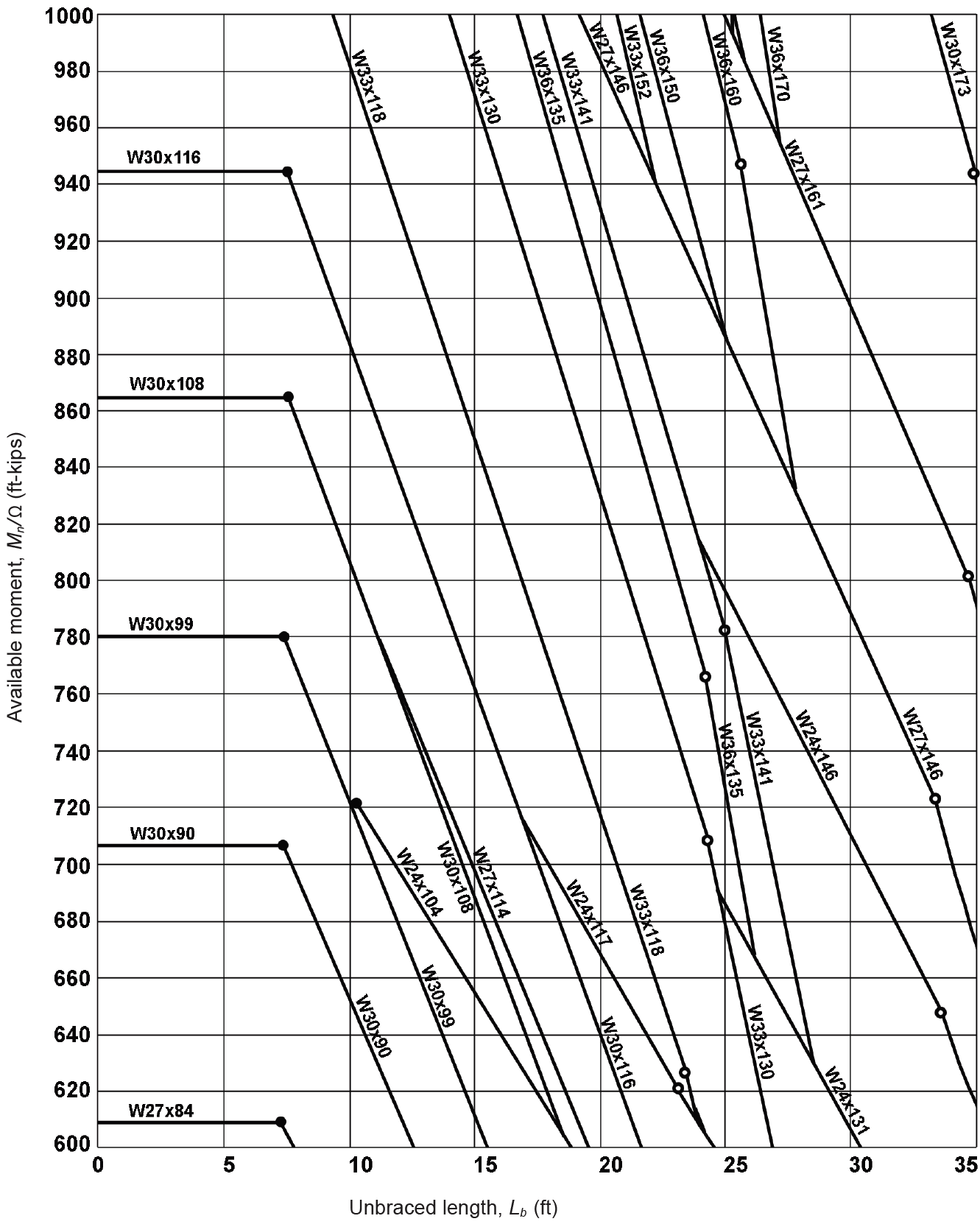
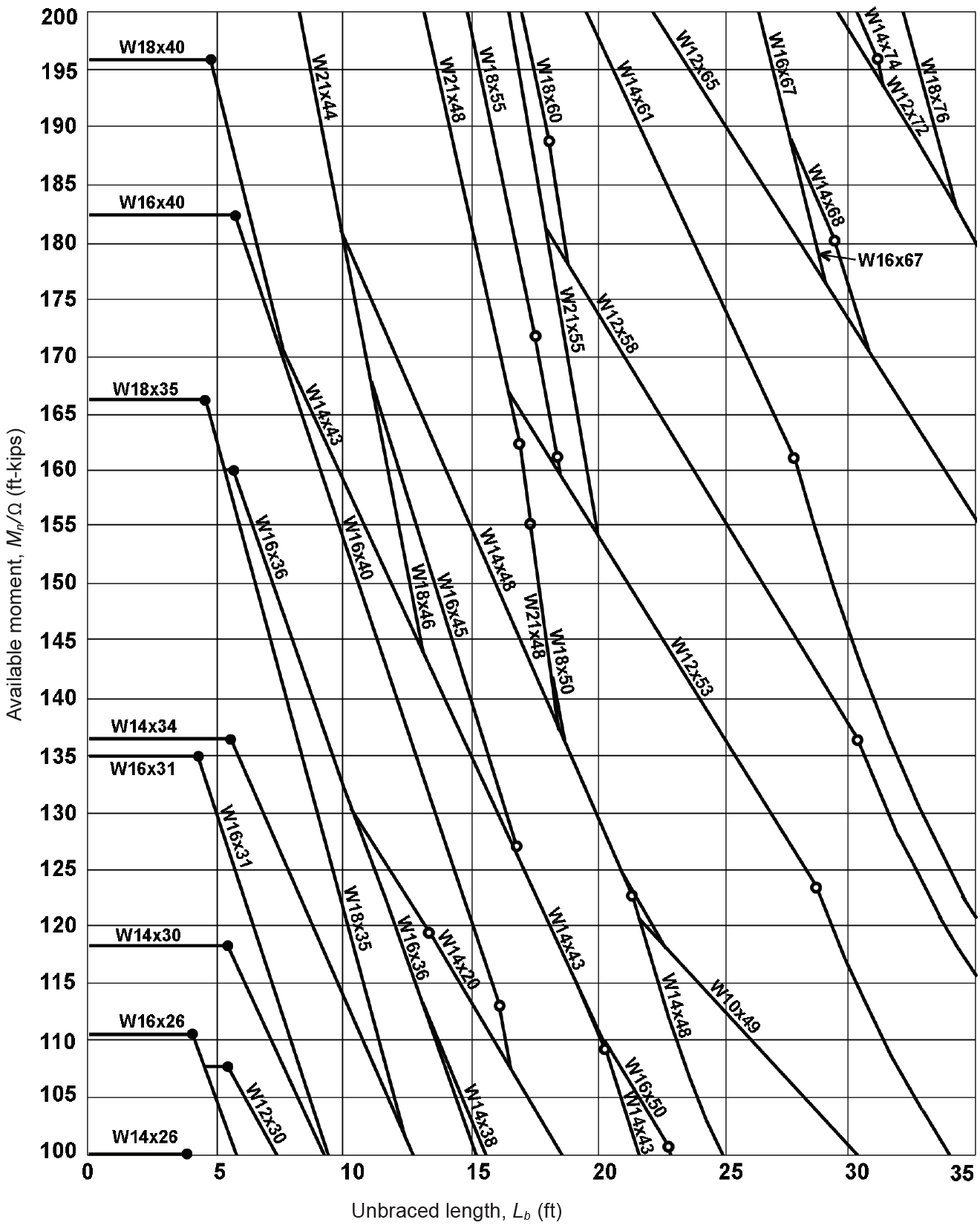
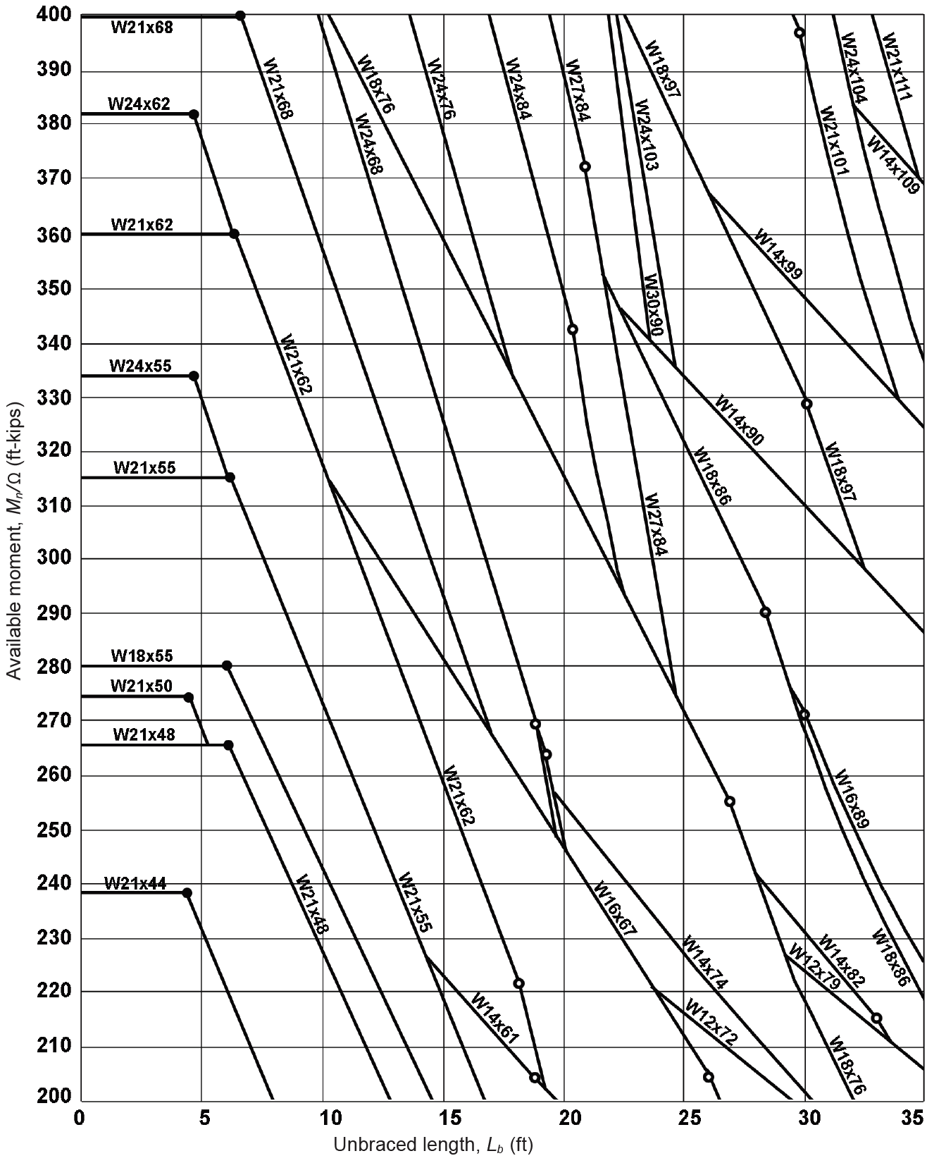
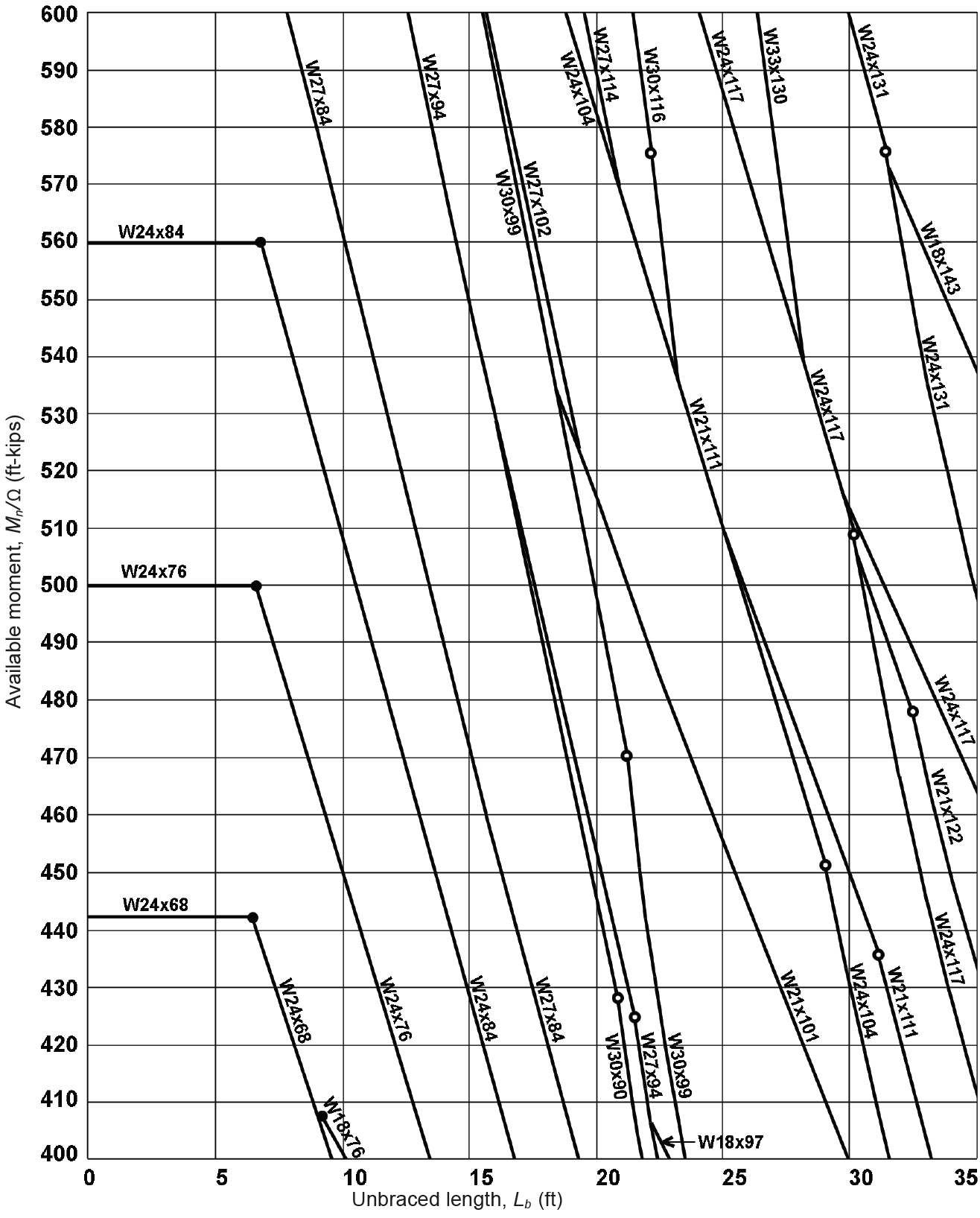
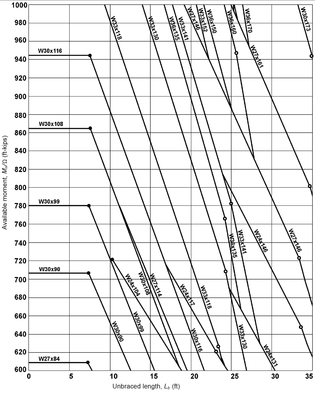
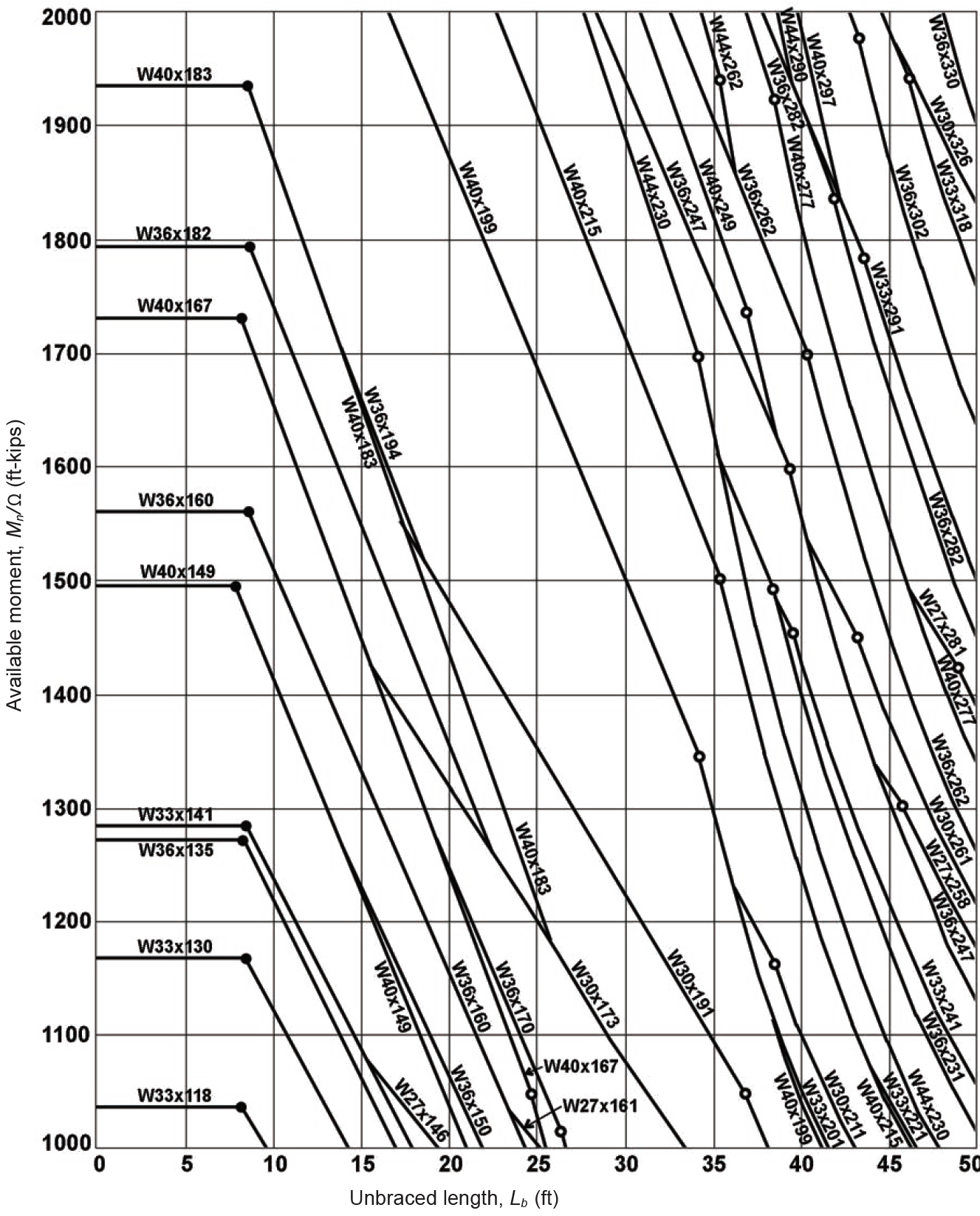
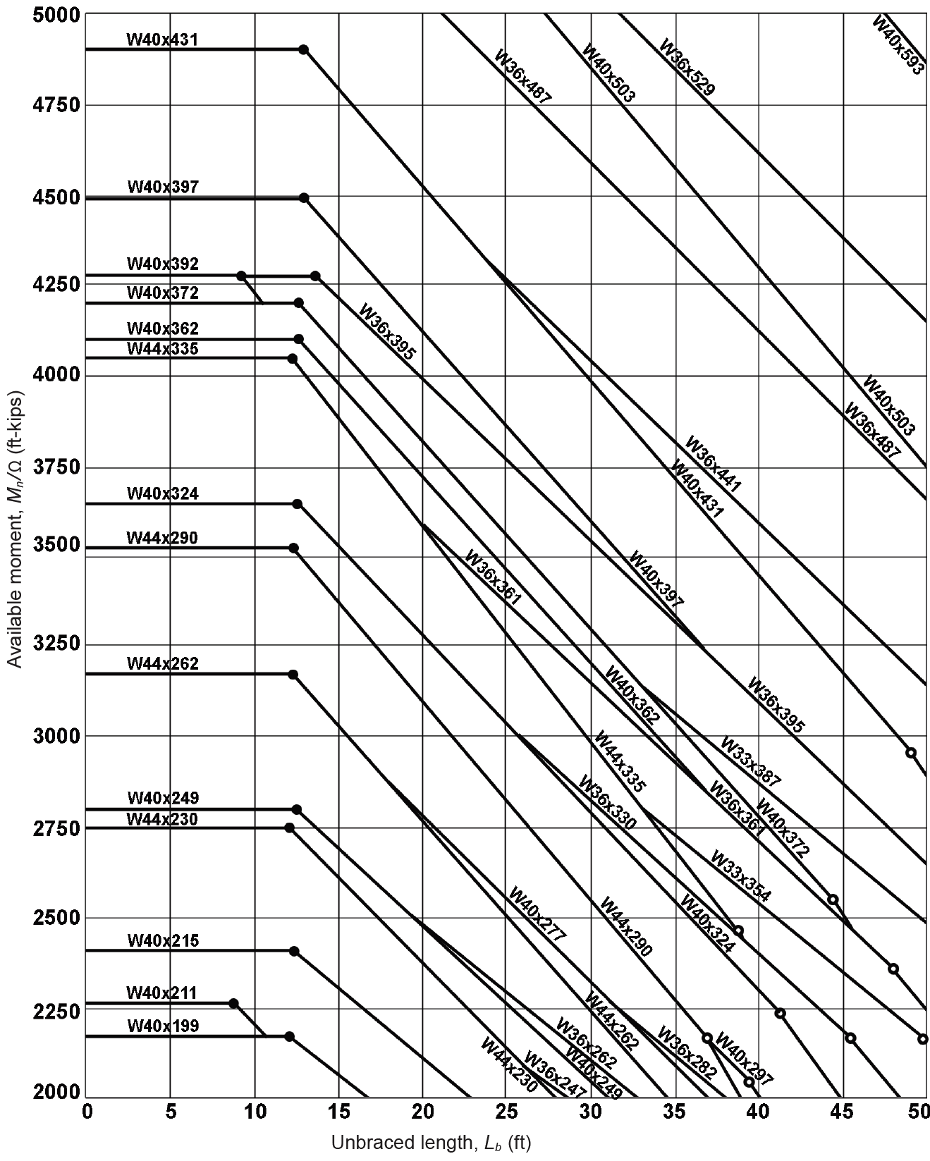
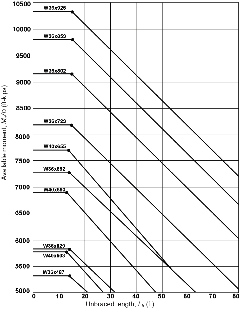
Table A-4.16: Available moment for A992 wide-flange (W) shapes1,2
| A. Available moments from 0 to 100 ft-kips |
|---|
 |
| B. Available moments from 100 to 200 ft-kips |
|---|
 |
| C. Available moments from 200 to 400 ft-kips |
|---|
 |
| D. Available moments from 400 to 600 ft-kips |
|---|
 |
| E. Available moments from 600 to 1000 ft-kips |
|---|
 |
| F. Available moments from 1000 to 2000 ft-kips |
|---|
 |
| G. Available moments from 2000 to 5000 ft-kips |
|---|
 |
| H. Available moments from 5000 to 8000 ft-kips |
|---|
 |
Notes:
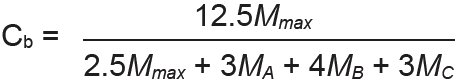
1. Values are based on the conservative assumption that the "lateral-torsional buckling modifier," Cb = 1.0. This conservative value of Cb = 1.0 is quite close to the actual value for simply-supported beams with equally spaced point loads of equal weight, where the beam is braced at those points only, except for the special case of a single point load at midspan, in which case Cb = 1.364. Actual values for Cb can be found for each unbraced beam segment by calculating the bending moments at the quarter-points along each segment (MA, MB, and MC, with MB being the moment at the midpoint of the segment), as well as the maximum moment, Mmax, within each segment, and then inserting these values into Equation 4.13, reproduced as follows:
In any case, the available moment cannot exceed Mp / Ω, the value for braced, compact sections given in Appendix Table A-4.15.
2. Solid circles represent the maximum unbraced length, Lp, for which a plastic moment can be achieved before the onset of lateral-torsional buckling; open circles represent the maximum unbraced length, Lr, for which an elastic moment can be achieved before the onset of lateral-torsional buckling (see Figure 4.24).
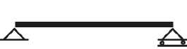
Table A-4.17: Maximum (actual) deflection in a beam1,2,3
Deflection coefficient, C, for maximum (actual) deflection, Δ (in.), where Δ = 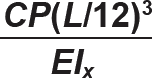 | ||||
 |  |  |  | |
 | 22.46 | 9.33 | 4.49 | 216 |
 | 35.94 | 16.07 | 8.99 | n/a |
 | 61.34 | 26.27 | 13.31 | n/a |
 | 85.54 | 36.12 | 17.97 | n/a |
 | n/a | n/a | n/a | 576 |
Notes:
1. Beam diagram symbols in top row of tables represent the following conditions (from left to right): simply-supported; one end pinned and one end continuous; both ends continuous; and cantilever.
2. Units for the maximum (actual) deflection equation are as follows:
Δ = maximum (actual) deflection (in.)
C = deflection coefficient
L = span (in.): The quantity (L /12) that appears in the deflection equation is therefore the span in feet
E = modulus of elasticity (psi when load is in lb; or ksi when load is in kips)
Ix = moment of inertia about axis of bending (in4)
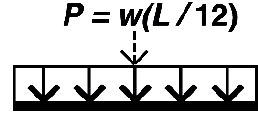
P = concentrated load or resultant of uniformly-distributed load (lb or kips)
w = uniformly-distributed load (lb/ft or kips/ft)
3. Allowable deflections (from Appendix Table A-1.3) are as follows:
For live load only (or snow or wind only), the typical basic floor beam limit is L/360 while typical roof beam limits are L/180, L/240, or L/360 (for no ceiling, nonplaster ceiling, or plaster ceiling respectively).
For total loads (combined live and dead), the typical basic floor beam limit is L/240 while typical roof beam limits are L/120, L/180, or L/240 (for no ceiling, nonplaster ceiling, or plaster ceiling respectively).
Table A-4.18: Shear capacity, or available strength, for a high-strength bolt subjected to single shear with threads excluded from shear plane (kips)
| A. Bearing-type connections1 | ||||||||
|---|---|---|---|---|---|---|---|---|
| Bolt type | Nominal bolt diameter (in.) | |||||||
| ⅝ | ¾ | ⅞ | 1 | 1⅛ | 1¼ | 1⅜ | 1½ | |
| Group A (A325) | 10.4 | 15.0 | 20.4 | 26.7 | 33.8 | 41.8 | 50.3 | 60.2 |
| Group B (A490) | 12.9 | 18.6 | 25.2 | 33.0 | 41.7 | 51.7 | 62.2 | 74.3 |
| Group C (F3043) | — | — | — | 44.4 | 56.2 | 69.5 | — | — |
| B. Slip-critical connections (based on strength rather than serviceability)2 | ||||||||
|---|---|---|---|---|---|---|---|---|
| Bolt type | Nominal bolt diameter (in.) | |||||||
| ⅝ | ¾ | ⅞ | 1 | 1⅛ | 1¼ | 1⅜ | 1½ | |
| Group A (A325) | 4.29 | 6.33 | 8.81 | 11.5 | 12.7 | 16.0 | 19.2 | 23.3 |
| Group B (A490) | 5.42 | 7.91 | 11.1 | 14.5 | 18.1 | 23.1 | 27.3 | 33.4 |
| Group C (F3043) | — | — | — | 20.3 | 25.5 | 32.3 | — | — |
Notes:
1. Capacities are tabulated for single-shear connections, with bolt threads excluded from all shear planes (condition X). For double-shear, multiply values by 2; for threads included within shear planes (condition N), multiply values by 0.8. For double-shear and threads included, multiply by 2 × 0.8 = 1.6.
2. Slip-critical capacities are based on standard holes and single-shear. For double shear, multiply values by 2. Slip-critical bolts must also satisfy bearing capacity values in Appendix Table A-4.19.
Table A-4.19: Bearing capacity, or available strength, for a high-strength bolt bearing on material 1 in. thick, with clear spacing between bolts (or edge) ≥ 2 in. (kips)1
| Material being connected | Nominal bolt diameter (in.) | |||||||
|---|---|---|---|---|---|---|---|---|
| ⅝ | ¾ | ⅞ | 1 | 1⅛ | 1¼ | 1⅜ | 1½ | |
| A36, Fu = 58 ksi | 54.4 | 65.3 | 76.1 | 87.0 | 97.9 | 109 | 120 | 131 |
| A992, Fu = 65 ksi | 60.9 | 73.1 | 85.3 | 97.5 | 110 | 122 | 134 | 146 |
Note:
1. Capacity (available strength) is tabulated assuming that the bolt hole clear spacing (or clear spacing between bolt hole and material edge) in direction of force is no less than 2 in. For clear spacing less than 2 in., multiply capacity by Lc/ 2, where Lc is the actual clear spacing (in.). For cases where the small deformations associated with bolt bearing, at ordinary service loads, are considered to be a design issue, multiply capacity by 0.8. Where the thickness, t, of the material is other than 1 in., multiply the capacity by the thickness, t (in.). These multiplications are cumulative so that, for example, the capacity of a material with t = ⅝ in., clear spacing between bolts of 1.75 in., and consideration of bearing deformations, would be equal to the tabular value multiplied by (⅝)(1.75/2)(0.8) = (tabular value × 0.4375).
Table A-4.20: Minimum and maximum spacing and edge distance measured from bolt centerline for standard holes
| A. Minimum bolt spacing (in.) | ||||||||
|---|---|---|---|---|---|---|---|---|
| Nominal bolt diameter (in.) | ||||||||
| ⅝ | ¾ | ⅞ | 1 | 1⅛ | 1¼ | 1⅜ | 1½ | |
| Suggested | 1⅞ | 2¼ | 2⅝ | 3 | 3⅜ | 3¾ | 4⅛ | 4½ |
| Required | 1⅔ | 2 | 2⅓ | 2⅔ | 3 | 3⅓ | 3⅔ | 4 |
| B. Minimum edge distance (in.)1 | ||||||||
|---|---|---|---|---|---|---|---|---|
| Type of edge | Nominal bolt diameter (in.) | |||||||
| ⅝ | ¾ | ⅞ | 1 | 1⅛ | 1¼ | 1⅜ | 1½ | |
| All edges | ⅞ | 1 | 1⅛ | 1¼ | 1½ | 1⅝ | 1-23/32 | 1⅞ |
| C. Maximum bolt spacing and edge distance (in.) | ||||||||
|---|---|---|---|---|---|---|---|---|
| Type of edge | Nominal bolt diameter (in.) | |||||||
| ¼ | ⅜ | ½ | ⅝ | ¾ | ⅞ | 1 | 1⅛ | |
| Centerline spacing2 | 6 | 9 | 12 | 12 | 12 | 12 | 12 | 12 |
| Edge distance | 3 | 4½ | 6 | 6 | 6 | 6 | 6 | 6 |
Notes:
1. Minimum edge distances, measured in the direction of force, may be reduced below these values, as long as bearing capacity is appropriately reduced (see Note 1 in Appendix Table A-4.19). Bearing and tearout limits must also be met.
2. Maximum centerline spacing is measured in the direction of the applied load (longitudinally), and is valid for members not subject to corrosion, whether painted or not. For unpainted weathering steel, the maximum spacing is 7 in. or, where the thinner member is less than ½ in., 14 times that member's thickness.
Table A-4.21: Size limitations (leg size, w) for fillet welds (in.)
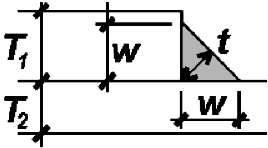 | Thickness, T, of material being joined (in.)1 | ||||
|---|---|---|---|---|---|
| T < ¼ in. | T = ¼ in. | ¼ < T ≤ ½ in. | ½ < T ≤ ¾ in. | ¾ < T | |
| Minimum weld size, w | 1/8 | 1/8 | 3/16 | 1/4 | 5/16 |
| Maximum weld size, w | T | 3/16 | T – 1/16 in. | ||
© 2020 Jonathan Ochshorn; all rights reserved. This section first posted November 15, 2020; last updated November 15, 2020.