
Contents |
Introduction to structural design | Statics |
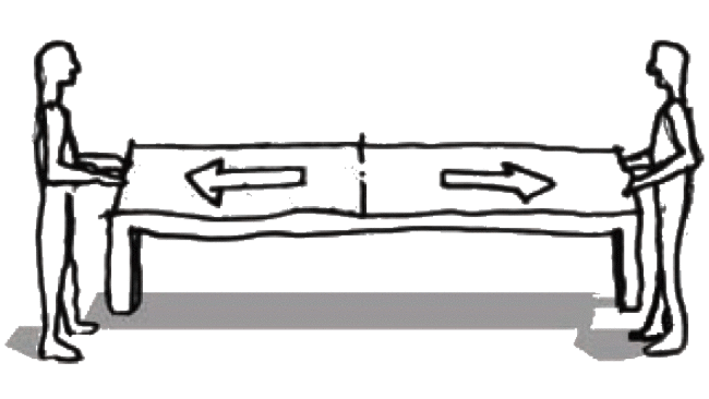
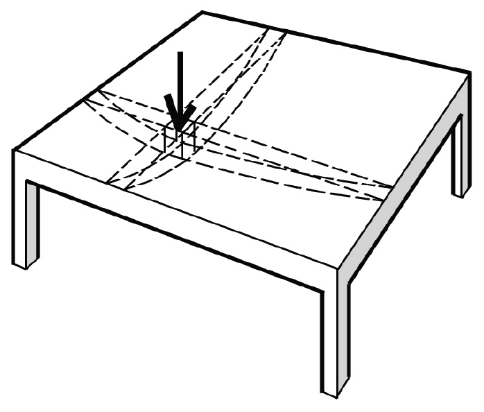
When loads are evenly distributed over a surface, it is often possible to "assign" portions of the load to the various structural elements supporting that surface by subdividing the total area into tributary areas corresponding to each member. In Figure 1.3, half the load of the table goes to each lifter.
In Figure 1.4, half the 20-psf snow load on the cantilevered roof goes to each column; the tributary area for each column is 10 ft × 10 ft, so the load on each column is 20(10 × 10) = 2000 lb = 2 kips.
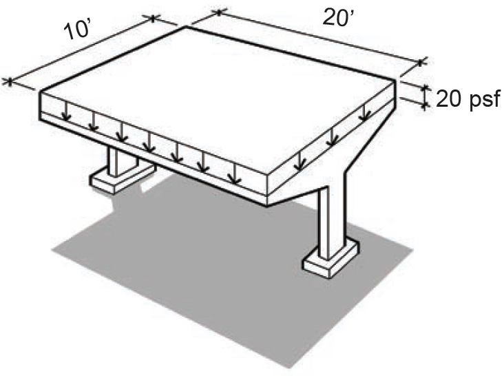
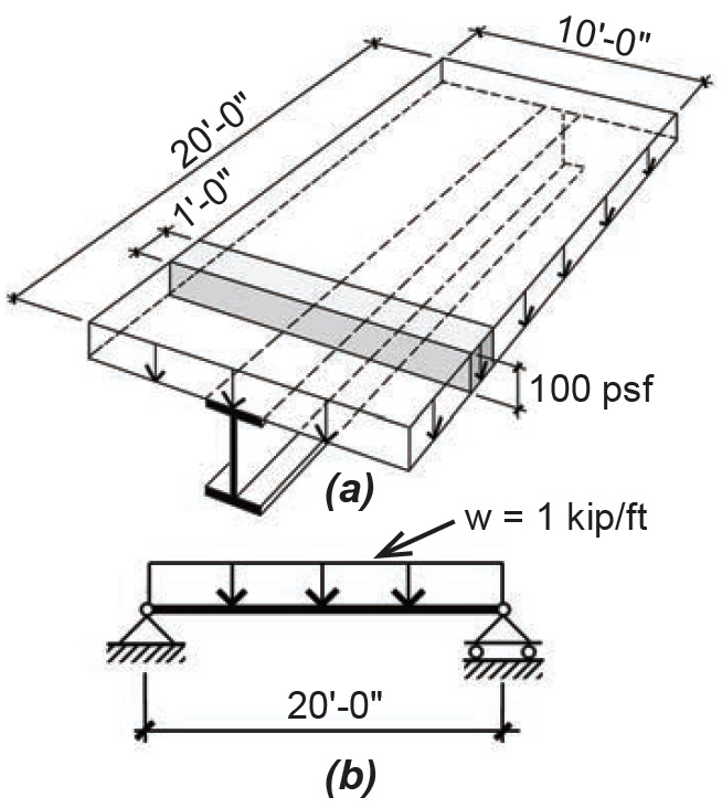
Figure 1.5 shows a framing plan for a steel building. If the total floor load is 100 psf, the load acting on each of the structural elements comprising the floor system can be found using appropriate tributary areas. Beam A supports a total load of 100(20 × 10) = 20,000 lb = 20 kips; but it is more useful to calculate the distributed load acting on any linear foot of the beam — this is shown by the shaded tributary area in Figure 1.6a and is 100(1 × 10) = 1000 lb = 1 kip. Since 1000 lb is acting on a 1-ft length of beam, we write 1000 lb/ft or 1.0 kip/ft, as shown in Figure 1.6b.
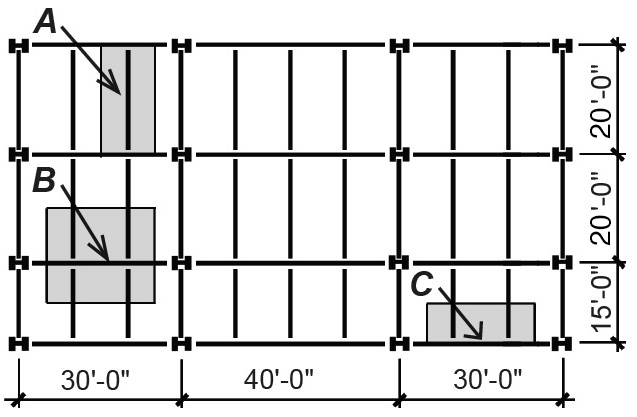
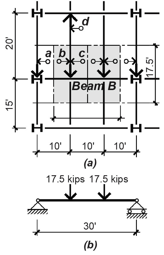
As shown in Figure 1.7a, Beam B (or Girder B) supports a total tributary area of 17.5 × 20 = 350 ft2. The load at point a is not included in the beam's tributary area. Rather, it is assigned to the edge, or spandrel, beam where it goes directly into a column, having no effect on Beam B. Unlike Beam A, floor loads are transferred to Beam B at two points: each concentrated load corresponds to a tributary area of 17.5 × 10 = 175 ft2; therefore, the two loads each have a magnitude of 100 × 175 = 17,500 lb = 17.5 kips. The load diagram for Beam B is shown in Figure 1.7b.
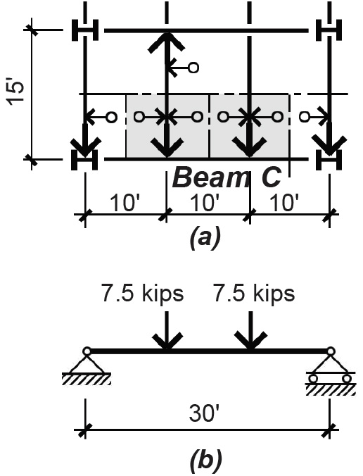
Beam C (or spandrel girder C), shown in Figure 1.5, is similar to Beam B except that the tributary area for each concentrated load is smaller, 7.5 × 10 = 75 ft2, as shown in Figure 1.8a. The two concentrated loads, therefore, have a magnitude of 100 × 75 = 7500 lb = 7.5 kips, and the load diagram is as shown in Figure 1.8b.
There are three reasons spandrel girders are often larger than otherwise similar girders located in the interior of the building, even though the tributary areas they support are smaller. First, spandrel girders often support cladding of various kinds, in addition to the floor loads included in this example. Second, aside from the added weight to be supported, spandrels are often made bigger so that their deflection, or vertical movement, is reduced. This can be an important consideration where nonstructural cladding is sensitive to movement of the structural frame. Third, when the girders are designed to be part of a moment-resisting frame, their size might need to be increased to account for the stresses introduced by lateral forces such as wind and earthquake.
One way or another, all of the load acting on the floor must be carried by columns under that floor. For most structures, it is appropriate to subdivide the floor into tributary areas defined by the centerlines between columns so that every piece of the floor is assigned to a column.
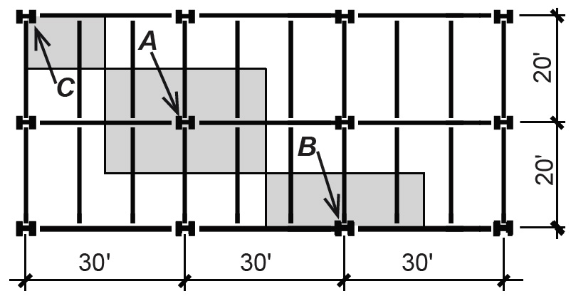
It can be seen from Figure 1.9 that typical interior columns (Column A) carry twice the load of typical exterior columns (Column B), and four times the load of corner columns (Column C). However, two of the conditions described earlier with respect to the enlargement of spandrel girders can also increase the size of exterior and corner columns: the need to support additional weight of cladding and the possibility of resisting wind and earthquake forces through rigid connections to the spandrel girders.
Column A in Figure 1.9 supports a tributary area of 30 × 20 = 600 ft2 so that the load transferred to Column A from the floor above is 100 × 600 = 60,000 lb = 60 kips, assuming that the floor above has the same shape and loads as the floor shown. But every floor and roof above also transfers a load to Column A. Obviously, columns at the bottom of buildings support more weight than columns at the top of buildings, since all the tributary areas of the floors and roof above are assigned to them. As an example, if there are nine floors and one roof above Column A, all with the same distributed load and tributary area, then the total load on Column A would be, not 60 k, but (9 + 1) × 60 = 600 kips.
In practice, the entire load as previously calculated is not assigned to columns or to other structural elements with large total tributary areas. This is because it is unlikely that a large tributary area will be fully loaded at any given time. For example, if the live load caused by people and other movable objects is set at 60 psf, and one person weighed 180 lb, then a tributary area of 600 × 9 = 5400 ft2 (as in the example of Column A, but discounting the roof area) would have to be populated by 1800 people, each occupying 3 ft2, in order to achieve the specified load. That many people crowded into that large a space is an unlikely occurrence in most occupancies, and a live load reduction is often allowed by building codes. As the tributary area gets smaller, however, the probability of the full live load being present increases, and no such reduction is permitted. Permanent and immovable components of the building, or dead loads, have the same probability of being present over large tributary areas as small tributary areas, so they are never included in this type of probability-based load reduction. Calculations for live load reduction are explained in the next chapter.
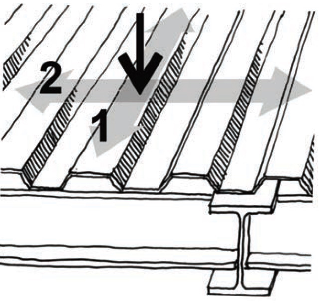
The path taken by a load depends on the ability of the structural elements to transfer loads in various directions. Given the choice of two competing load paths such as (1) and (2) in Figure 1.10, the load is divided between the two paths in proportion to the relative stiffness of each path. Since the corrugated steel deck shown in Figure 1.10 is much stiffer in the direction of load path (1), and, in fact, is designed to carry the entire load in that direction, we neglect the possibility of the load moving along path (2).
For "two-way" systems, generally only used in reinforced concrete (Figure 1.11), or for indeterminate systems in general, the assignment of loads to beams and columns also becomes a function of the relative stiffness of the various components of the system. Stiffer elements "attract" more load to them, and the simplistic division into tributary areas becomes inappropriate, except in certain symmetrical conditions.
© 2020 Jonathan Ochshorn; all rights reserved. This section first posted November 15, 2020; last updated February 5, 2021.