
Contents |
Introduction to structural design | Statics | Tributary areas | Equilibrium | Reactions | Internal forces | Indeterminate structure | Material properties | Strength of materials | Sectional properties |
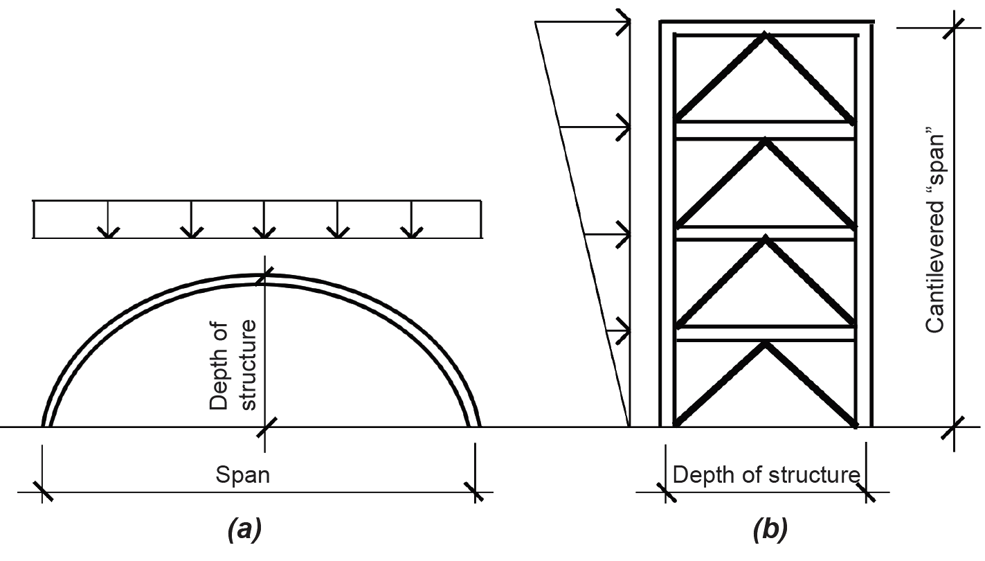
Structural systems can be extremely complex, and their behavior and design can be incredibly nuanced and sophisticated. However, at a basic level, there are really only two relevant aspects to the design of structural systems: with respect to floors, the structure must accommodate the human need for horizontal surfaces upon which to walk, sit, sleep, and so on; with respect to roofs — in particular, long-span roofs where there is no such requirement for horizontal walking surfaces — an efficient structure must "find a form" that prioritizes axial stresses, reduces bending stresses, and maximizes the overall depth (height) of the spanning geometry. This last point bears repeating. To the extent that the structural system is made "deep" in the direction of applied loads, internal stresses will be reduced, making constituent structural elements that comprise the system that much smaller. This is true not only of long-span roof structures (Figure 1.70a), but also of tall buildings or towers subjected to lateral (wind or seismic) loads. For such tall buildings, the "depth" is really the building width where the building itself is modeled as a vertical span cantilevered out of the ground, subjected to lateral forces (Figure 1.70b).
Floor structures are inherently inefficient because it rarely makes sense to increase the depth of the floor in order to increase structural efficiency — doing so might reduce stresses in the floor, but would create enormous inefficiencies in the overall building form. We therefore typically use ordinary beams, girders, slabs, and decks to make floors, rather than using deeper, and potentially more efficient, spanning elements. For long-span roofs or tall buildings, however, efficiency becomes paramount, especially because deflections increase proportionally with the fourth power of the span (Equation 1.20).
The structural elements described in this book — tension elements or hangers, columns, and beams — are assembled into structural systems that must provide strength, stiffness, and stability. Strength refers to the ability to resist internal stresses up to a limit state modified (reduced) by a factor of safety. Stiffness refers to the resistance to movement, whether axial deformation in the case of tension elements and columns, or deflection in the case of beams. Stability is required in compressive elements so that they don't buckle, but more generally in structural systems as a whole so that they maintain their intended geometry even when loaded. Because vertical loads (live and dead "gravity" loads) can most often be transferred to a building's foundation without adversely affecting the stability of the building as a whole, whereas horizontal ("lateral") loads originating with wind or seismic events can often challenge a building's stability (think of a house of cards), a lateral-force-resisting system not only must be part of every structural system but is the key to the structure's stability.
Aside from the design of innovative long-span or tall-building geometries, this last requirement is actually what makes structural design most interesting: whereas adequate strength and stiffness can be achieved simply by making structural elements as large as required — by calculating their size — the stability of a structural system must be adequately conceptualized before any calculations are made. Fortunately, there really are only three alternative strategies for the design of such lateral-force-resisting systems: shear walls, triangulation (trusses, braces, buttresses, etc.), or rigid (moment-resisting) joints (Figure 1.71).
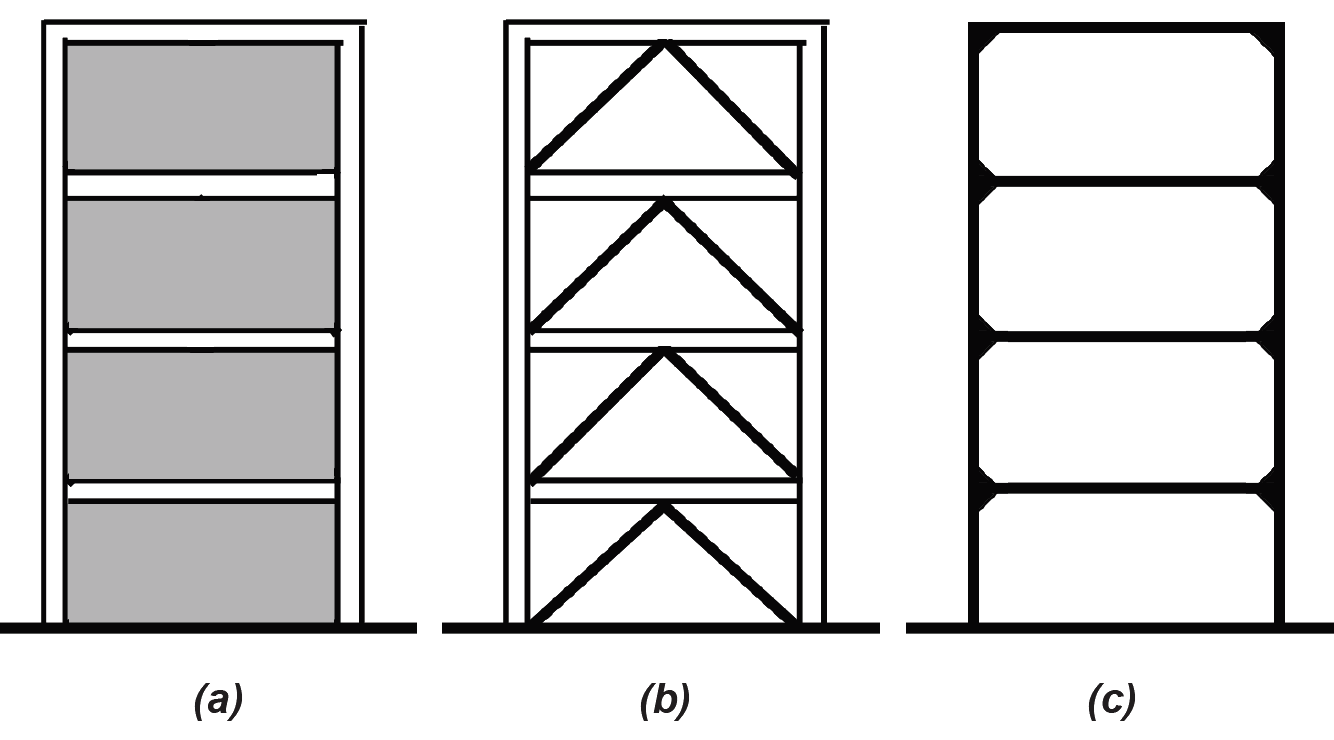
Masonry and reinforced concrete walls can serve as shear walls, as can wood "diaphragms" consisting of vertical studs, horizontal plates, and sheathing boards (Figure 1.71a). To the extent that such "solid" surfaces resist deformation, they keep a building stable. Where such systems are already used to support the live and dead loads of floors and roofs, it usually makes sense to take advantage of their inherent lateral stability as well.
Placing diagonal elements within the rectangular geometry of framed structures (i.e., structures otherwise consisting of columns and beams, rather than walls) is probably the most efficient way to achieve stability (Figure 1.71b). Triangles are inherently stable forms, in that they cannot be deformed without changing the length of their bounding elements in both compression and tension. In contrast, rectangular frames can be deformed into parallelograms without changing the length of any of their bounding elements, especially when the joints between these elements offer little or no resistance to rotation.
In fact, where the joints between columns and beams in a rectangular geometry are made rigid (moment-resisting) so that rotation is prevented, we get the third, and least-efficient, strategy for stability: the rigid, or moment-resisting, frame (Figure 1.71c). The reason for the relative inefficiency of such rigid frames can best be understood by comparing a triangulated and rigid frame structure, each modeled as a 1-story, 1-bay building subjected to a single 2000 kip horizontal load at the "roof" and consisting of rectangular 10 in. × 20 in. vertical and horizontal structural elements (Figure 1.72). Using truss analysis (see Example 1.6, section method), it can be seen that the maximum axial force in the triangulated structure is 2000 kips (in the horizontal "roof" element closest to the load). Since the cross-sectional area of that horizontal element is assumed to be 10 × 20 = 200 in2, the axial compressive stress (Equation 1.15) = force/area = 2000/200 = 10 ksi.
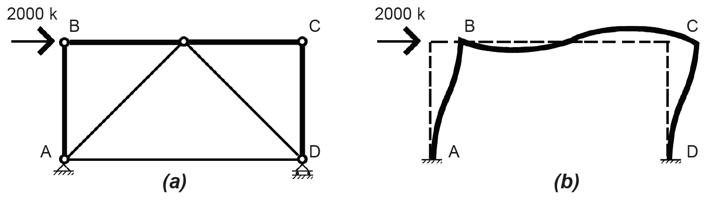
Now let's examine the stress within the rigid frame, subject to the same 2000 kip horizontal load. Because this is an indeterminate structure, we will make some simplifying assumptions so that it can be analyzed using only the three equations of equilibrium: first, that points of inflection (with zero bending moment) occur at the midpoints of all elements as the rigid frame deforms under the load; second, that the two horizontal shear forces at these inflection points split the 2000 kip external load equally between them; and third, that the frame dimensions are 10 ft high and 20 ft across. With these assumptions, we can cut the frame into four free-body diagrams and solve for the unknown axial and shear forces, starting with the top, left section (Figure 1.73). The bending moment at the top-left corner, point B, is therefore 500 × 10 = 5000 ft-k or, multiplying by twelve, 60,000 in-k. The section modulus (see the derivation for rectangular sections immediately after Equation 1.11) of the 10 × 20 cross section is 10 × 202/6 = 666.67 in3. The bending stress (Equation 1.23) is therefore equal to M/S = 60,000/666.67 = 90 ksi. The axial stress in the horizontal member = force/area = 1000/200 = 5 ksi, so the total maximum stress is actually 95 ksi.
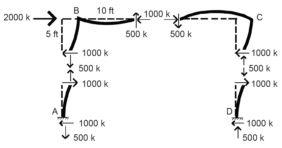
In other words (even ignoring the axial component), stresses in the rigid frame (90 ksi) are nine times greater than stresses in the triangulated structure (10 ksi) in this admittedly simplified example. Looked at in another way, the horizontal and vertical elements would need to have a section modulus nine times greater than the required section modulus of the structural elements in the triangulated structure in order to keep internal stresses at the same levels — resulting in cross-sectional dimensions of about 20 in. × 40 in. instead of 10 in. × 20 in. Not only that, lateral movement (deflection) in the more flexible rigid frame will also be much greater than in the triangulated structure. The rigid frame is inefficient as a lateral-force-resisting system because the magnitude of its internal stresses and its tendency to deflect are primarily determined by the "depth" (actually the section modulus, or moment of inertia in the case of deflection) of individual framing elements, rather than by the "depth" of the structural system as a whole.
A final point about lateral-force-resisting systems: they are typically deployed along two structural lines in each of two orthogonal directions. Two lateral-force-resisting elements are used in each orthogonal direction because a single element would have difficulty dealing with torsional (twisting) movements of the structure as a whole if the resultant of the applied load were not perfectly aligned with it. Such pairs of lateral-force-resisting elements are placed in each of two orthogonal directions since lateral forces (wind or seismic) can come from any direction. If such a lateral force arrives at an angle different from either of the two orthogonal axes, that force can be resolved into two orthogonal components aligned with the lateral-force-resisting elements — such components will always be smaller than the original force, so that a design based on the assumption that lateral forces may arrive in either of the two orthogonal directions is generally safe.
However, just providing a lateral-force-resisting system is not enough: somehow, all the other structural elements in the building must be adequately connected to the lateral-force-resisting system so that they, too, remain stable. This is often accomplished by considering the floor structures, consisting of beams, girders, slabs, and decks, as rigid (or semi-rigid) diaphragms that — because they are attached to the lateral-force-resisting system — keep the rest of the structure in its intended alignment (Figure 1.74).
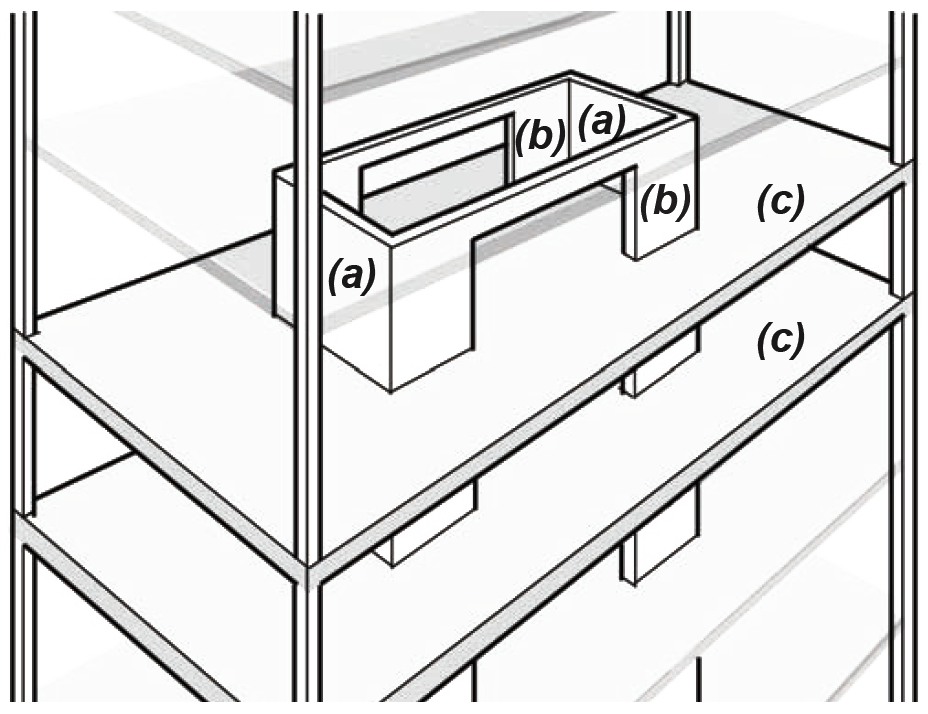
For long-span structures, the concept of a funicular shape — one that resolves all external loads into internal axial forces — is useful, since we have already seen in the case of the rigid frame that a strategy of resisting internal bending moments is inherently inefficient. A cable will always find its funicular shape, since it is incapable of resisting anything other than internal axial tension forces; therefore, optimal compressive shapes can be visualized by literally modeling them in tension and then "flipping them" over into compressive forms. Such idealized axial forms can then be used to gain insight into non-ideal geometries, since any geometric deviation from the ideal form corresponds to the magnitude of internal bending moments that would result, and therefore to the requirement for an increased section modulus in proportion to the geometric deviation (Figure 1.75).
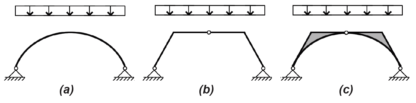
The concept of the funicular curve also explains why floor structures are almost always structurally inefficient: the idealized form under a floor's uniformly distributed load, as in the curve shown in Figure 1.75a, would be a parabolic vault or arch (think of the cable shape supporting the horizontal roadway of a suspension bridge), a shape not at all consistent with the efficient stacking of habitable space in multi-story buildings.
In spite of the potential complexity of structural systems — especially indeterminate systems subject to, and designed to account for, dynamic loads such as those caused by wind or seismic events, or geometrically complex 3-dimensional structures like hyperbolic paraboloids, whose behavior cannot easily be translated into 2-dimensional diagrams — the discussion of simple structural elements remains relevant. In the final analysis, even the most complex systems are often composed of structural elements subject to tension, compression, and bending moments, and so the procedures developed in this book are, in principle, applicable to the design of individual elements comprising more complex systems. Of course, the actual design and analysis of such complex systems, typically accomplished with structural analysis software, is beyond the scope of this book, but insights gained into the behavior and design of the simpler elements from which they are assembled is a useful first step.
© 2020 Jonathan Ochshorn; all rights reserved. This section first posted November 15, 2020; last updated November 15, 2020.