
Contents |
Introduction to structural design | Statics | Tributary areas |
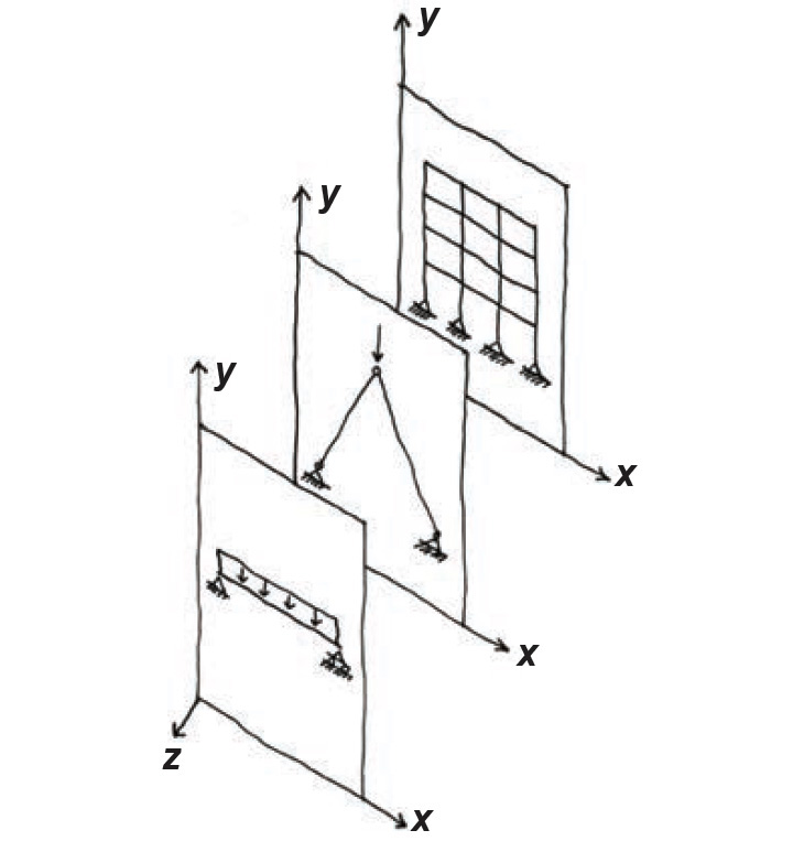
Where loads or structural geometries are not symmetrical, using tributary areas may not accurately predict the effects of loads placed on structures, and other methods must be used. We can determine the effects of loads placed on statically determinate structures by assuming that such structures remain "at rest," in a state of equilibrium. The implication of this condition, derived from Newton's second law, is that the summation of all forces (or moments) acting on the structure along any given coordinate axis equals zero. For a plane structure — i.e., one whose shape and deflection under loads occurs on a planar surface — three equations uniquely define this condition of equilibrium: two for loads (forces) acting along either of the perpendicular axes of the plane's coordinate system and one for moments acting "about" the axis perpendicular to the structure's plane. Some examples of plane structures are shown in Figure 1.12.
In words, the equations of equilibrium state that the sum of all "horizontal" forces is zero; the sum of all "vertical" forces is zero; and — take a deep breath here — the sum of all moments about any point, including those resulting from any force multiplied by its distance (measured perpendicular to the "line of action" of the force) to the point about which moments are being taken, is zero.
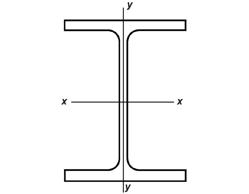
"Horizontal" and "vertical" can be taken as any perpendicular set of coordinate axes. Where x is used for the horizontal axis and y for the vertical, moments in the plane of the structure are acting about the z-axis. This conventional way of representing coordinate systems for the consideration of equilibrium is inconsistent with the labeling typically used to distinguish between axes of bending. Compare the typical axes of bending shown in Figure 1.13 with the "equilibrium" coordinate axes in Figure 1.12. Written symbolically, the equations are:
For any plane, rigid-body structure (just "structure" or "structural element" from now on) subjected to various loads, the three equations of equilibrium provide the mathematical basis for determining values for up to three unknown forces and moments — the reactions of the structure to the loads. Structural elements of this type are statically determinate because the magnitudes of the unknown reactions can be determined using only the equations of static equilibrium.
Any structure (or part of a structure) so defined can be represented as a free-body diagram (FBD). All "external" loads acting on the FBD, all unknown "external" moments or forces at the points where the FBD is connected to other structural elements (i.e., all reactions), and all unknown "internal" moments or forces at points where a FBD is "cut" must be shown on the diagram.
Single or multiple reactions occurring at a given point are often represented by standard symbols. These pictures graphically indicate the types of forces and moments that can be developed (Figure 1.14). Other combinations of forces and moments can be represented graphically; the three symbols shown, however, cover most commonly encountered conditions.
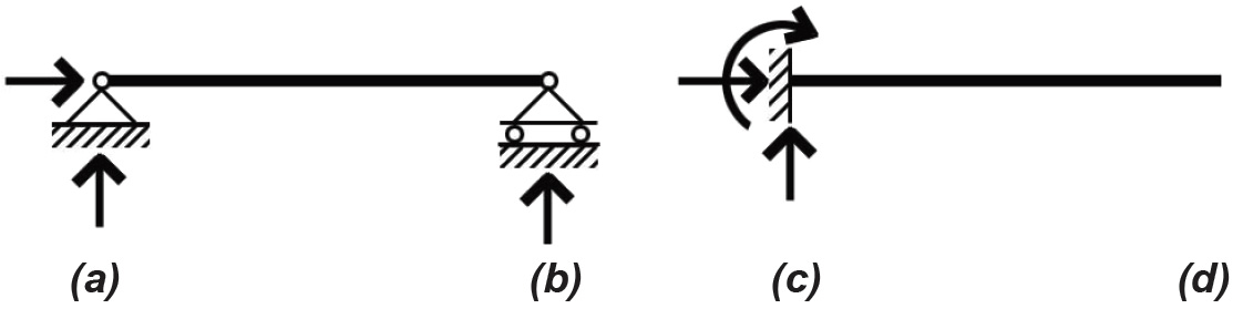
Where an FBD is "cut" at a point other than at the reactions of the structural element, an internal moment as well as two perpendicular internal forces are typically present, unless an internal constraint, such as a hinge, prevents one or more of those forces (or moments) from developing.
Where there are more reactions than equations of equilibrium, the structure is said to be statically indeterminate (redundant), and equilibrium alone is insufficient to determine the values of the reactions; other techniques have been developed to find the reactions of indeterminate structures, but these are beyond the scope of this text.
© 2020 Jonathan Ochshorn; all rights reserved. This section first posted November 15, 2020; last updated November 15, 2020.